
ARCH-301 · Lesson 5 of 12 · 26 min
Building envelope
Luis Ortega, the façade engineer who worked as a glazier for ten years before he went back to school, comes to the studio in week five with a box of samples: a corner of a triple-glazed window with a fiberglass frame, a length of thermally broken clip for fixing cladding, a brick with a cast-in tie, a square of standing-seam metal roofing and a short piece of CLT wrapped in a self-adhered membrane. He puts them on the table and asks each student to pick up the one that will most affect their building. Most pick the window. Callum picks the clip. 'Good,' says Ortega. 'The window you can see on the drawing. The clip is what nobody draws, and it is where your wall quietly loses a fifth of its insulation.'
What the envelope of the Commons must do
The students learned in the materials and environmental systems courses that an envelope is a set of control layers, each with a job: a water control layer that sheds rain and snowmelt, an air control layer that stops air leaking through the wall, a vapor control layer that limits moisture diffusing into the wall from the warm side, and a thermal control layer that slows the flow of heat. The envelope must also carry wind and its own weight to the structure, resist impact at the street and the park, let in light and views where they are wanted and keep out sun where they are not, last for decades with reasonable maintenance and look like the building it belongs to. Ortega asks them to list the special demands of the Commons before choosing any assembly.
The list is long. The avenue wall faces north, takes the north-west wind, will be splashed with slush and salt from the street, and must be transparent at the ground floor for the zoning framework. The park wall faces south, carries the big views and must be shaded in summer. The saw-toothed roof has rows of north-facing glazing and valleys where snow will drift and water must drain without freezing. The roof as a whole is large, about 22,600 ft², and will be the main source of heat loss after the windows. The building's ground floor sits close to the level of the park on the south side, so the base of the wall must deal with splashing, snow piled against it and the occasional flood. And the client wants the structure's timber to be visible from inside, which means the insulation and the air and vapor control layers must all be outside the structure, where the timber can stay warm and dry.
Choosing the wall
Because the timber frame carries all the loads, the exterior walls of the Commons carry only their own weight and the wind. That frees the choice of wall. Ortega describes three options. The first is a site-built steel stud wall with exterior insulation and cladding, common in public buildings and well understood by builders, but with steel studs that conduct heat and need thick exterior insulation to compensate. The second is a prefabricated wood-frame panel, built in a factory with studs, cavity insulation, sheathing and a membrane, delivered to site in lengths of 28 feet to match the grid, and finished with exterior insulation and cladding. The third is CLT wall panels with all the insulation outside, simple and robust but using more wood than the wall needs for its job.
Callum chooses the prefabricated wood-frame panel. It fits the grid, which makes the panels repeat; it can be installed in winter and closed in quickly, protecting the timber structure from snow; its wood studs conduct far less heat than steel; and it has low embodied carbon. Ortega warns him of the panel's weak points. The joints between panels must be sealed continuously for the air barrier, which is easy in a factory and hard on site. The panels must be protected from rain between delivery and closing in. And the exterior insulation, which he will need to reach the energy target, must be held by clips or rails that pass through it to carry the cladding, and every one of them is a thermal bridge.
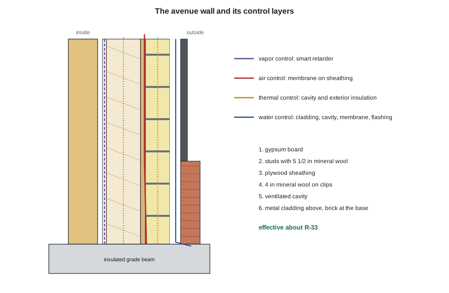
The wall's layers, from inside to outside, are: a gypsum board finish; the wood-frame panel with 5½ inches of mineral wool between studs; plywood sheathing with a vapor-permeable membrane that serves as both the air barrier and the water-resistive barrier; 4 inches of semi-rigid mineral wool outside the sheathing, held by thermally broken clips and rails; a ventilated cavity; and cladding. At the base of the avenue wall the cladding is brick, a reference to the brick foundations of the old rail shed that Callum photographed, and a material that can take slush, salt and bicycles. Above the first floor it is standing-seam metal in a dark gray, which recalls the corrugated sheds and weighs much less than brick. On the park side it is vertical larch boards, which will weather silver.
Callum has made a choice about the vapor control layer that Ortega approves. In the cold climate, warm humid air from inside must be kept from reaching the cold outer parts of the wall, where its moisture could condense. Because most of the insulation in the cavity is inside the sheathing, the wall needs a vapor retarder on the warm side; the environmental systems course showed that at −14 °F the sheathing would otherwise fall below the dew point of indoor air. The exterior insulation keeps the sheathing warmer than it would be without it, which reduces the risk, but does not remove the need for the retarder. Callum specifies a smart vapor retarder, a membrane whose permeance rises when it is humid, so that the wall can dry inward in summer.
How good is the wall?
The script below calculates the wall's effective thermal resistance by the parallel path method the students learned in the materials course: one path through the insulated cavity, one through the studs, combined by the framing fraction. It reduces the exterior insulation's value by a factor for the clips. It then compares the whole envelope's heat-loss coefficient, the sum of each area times its U-factor, with a reference building built to approximate prescriptive values of the energy code, for two window shares: the 43% of Callum's schematic design and the 30% that Sethi has suggested.
# Commons envelope: effective wall value, then UA against a code reference for two window shares
films, gyp, sheath, ext, cladding = 0.85, 0.45, 0.62, 16.0, 0.85   # thermal resistances (h ft2 F/Btu)
cavity, stud, frac = 22.0, 6.9, 0.23                     # cavity insulation, stud, framing fraction
clip_factor = 0.85                                           # exterior insulation lost to cladding clips
path_cav = films + gyp + cavity + sheath + ext * clip_factor + cladding
path_stud = films + gyp + stud + sheath + ext * clip_factor + cladding
r_wall = 1 / (frac / path_stud + (1 - frac) / path_cav)
print(f"wall: cavity path {path_cav:.1f}, stud path {path_stud:.1f}, effective {r_wall:.1f} h ft2 F/Btu")

wall_gross, roof = 24200, 22600                                 # gross wall and roof area (ft2)
u_wall, u_roof, u_win = 1 / r_wall, 1 / 51.0, 0.17         # proposed U-factors (Btu/h ft2 F)
ref_wall, ref_roof, ref_win, ref_share = 0.051, 0.032, 0.4, 0.4  # reference values (approximate)
for share in (0.43, 0.30):
    win = wall_gross * share
    ua = u_wall * (wall_gross - win) + u_roof * roof + u_win * win
    ref_glass = wall_gross * min(share, ref_share)
    ua_ref = ref_wall * (wall_gross - ref_glass) + ref_roof * roof + ref_win * ref_glass
    print(f"window share {share:.0%}: windows {win:5,.0f} ft2, UA {ua:5,.0f}, reference {ua_ref:5,.0f} Btu/h F "
f"-> {ua / ua_ref:.0%} of reference; windows carry {u_win * win / ua:.0%} of the loss")wall: cavity path 38.4, stud path 23.3, effective 33.4 h ft2 F/Btu window share 43%: windows 10,406 ft2, UA 2,625, reference 5,336 Btu/h F -> 49% of reference; windows carry 67% of the loss window share 30%: windows 7,260 ft2, UA 2,185, reference 4,491 Btu/h F -> 49% of reference; windows carry 56% of the loss
The wall comes out at about R-33 effective, which beats the reference wall comfortably. The roof, with R-51 of insulation above the CLT deck, does even better. But the windows tell the real story. At a window share of 43%, the windows carry two thirds of the building's envelope heat loss, though they are less than a quarter of its envelope area. Reducing the share to 30% cuts the total by about a sixth. It also keeps the building well inside the limit of 40% that the energy code's prescriptive path allows. Callum resists for a day, then accepts. He keeps the ground-floor glazing on the avenue, which the zoning framework requires and the commons needs, keeps the big south windows of the library and the gathering room, and reduces the upper-floor windows on the north to a pattern of tall, narrow openings set between the columns, with the saw-toothed roof bringing light from above.
Windows, glazing and the saw-toothed roof
Ortega spends the most time on the windows, because they are the most complicated element in the envelope and the one most often installed badly. The windows of the Commons will be triple-glazed, with low-emissivity coatings and an inert gas fill, in fiberglass frames that expand with temperature at about the same rate as glass and conduct little heat. The glass on the south must let in winter sun but be shaded from summer sun; Callum uses deep timber fins and an overhang sized by the method from the environmental systems course. The glass on the north, including the saw-toothed roof, can have a higher visible transmittance because it receives little direct sun.
Each window must be installed so that its four control layers connect to the wall's. The window's frame is sealed to the wall's air barrier with a membrane or a sealant joint that runs all the way round. The sill is sloped and flashed, with end dams that stop water from running off the ends of the flashing into the wall. The head is flashed to shed water from above. The frame sits in line with the insulation, not toward the outside of the wall where it would be cold, which keeps its inner surface warm and reduces the risk of condensation on the frame in winter. Ortega shows the class a photograph of a library he inspected where the windows had been set flush with the cladding for a crisp appearance: every winter the bottom of each frame was rimmed with ice on the inside.
The saw-toothed roof is the envelope's special problem. Each tooth has a sloped roof face and a near-vertical glazed face facing north, and between the teeth is a valley. Snow will drift into the valleys, and the meltwater must reach a drain without refreezing at the base of the glass. Ortega recommends three things. The valleys should be wide enough for a person to walk along and clear them, and should slope to drains placed inside the heated envelope so that they do not freeze. The glazing should start well above the valley floor, on an upstand at least as high as the expected drift, with the roof membrane carried up behind the glass. And the glazing should be an assembly designed and tested for sloped or vertical use in this climate, not ordinary windows set on their side.
The roof and the base
The flat parts of the roof are CLT panels with a vapor control layer on top, about 9 inches of insulation in two layers with staggered joints, a cover board and a single-ply membrane. The insulation is tapered to slope the roof to internal drains. Callum asks whether the roof could be green, with plants, as some of his classmates propose. Ortega says it could, but that a green roof on a timber deck needs careful attention to the membrane, to the weight of saturated soil and to the drift loads, and that its benefits here, slowing stormwater and cooling the roof in summer, are partly provided by the stormwater park next door. Callum decides on a white membrane, with space reserved on the south-facing parts of the roof for solar panels, which the energy lesson will size.
The base of the wall is where the envelope meets the ground and where many buildings fail. On the avenue the brick sits on a flashing over an insulated grade beam; the flashing directs any water in the cavity out of the wall above the sidewalk. On the park side, where snow will pile against the larch boards, the cladding stops 12 inches above the terrace, and the wall below is concrete with a protective board over its insulation. Insulation runs down the outside of the grade beams and out horizontally under the terrace to keep frost away from the foundations. On the compacted granular fill, the slab-on-grade's edge is insulated vertically and horizontally to keep frost from heaving the edge and the entrance thresholds.
Air tightness and testing
An envelope's insulation is wasted if air leaks through it. Ortega describes the airtightness test that the city will require for the Commons: the building is closed up, a large fan is fitted in a door, and the air leakage is measured at a fixed pressure difference, usually 75 Pa for large buildings. The brief sets a target that is common for high-performance public buildings: no more than 0.2 cfm per ft² of envelope area at that pressure. Meeting it depends on a continuous air barrier and on the care with which every joint is made. Ortega asks Callum to draw the air barrier as a single red line on his wall sections and plans, and to trace it without lifting his pencil from the foundation, up the wall, across the roof and down the other side. Where the pencil has to jump, at a window, a column, a duct or a roof drain, there must be a detail.
Callum's red line jumps fourteen times. Ortega goes through them with him. The window perimeters are the most common, and each will be detailed. The glulam columns that pass from inside to outside at the commons' canopy are the most difficult; Callum agrees to stop the columns inside the envelope and carry the canopy on separate steel posts. The roof drains, the plumbing vents, the kitchen exhaust from the café and the makerspace's dust extraction all pass through the roof and need sealed penetrations. And the joint between the prefabricated wall panels and the CLT roof panels, which will be made on site in winter, needs a membrane strip that the builder can install from outside without working on a ladder in the wind.
Worked problem
A thermal bridge at the canopy
In Callum's schematic design, the glulam columns of the entrance canopy are continuous with the columns inside the commons, passing through the wall. Each column is 10¾ × 10½ inches and there are four. Why does Ortega object, and what is the remedy?
Show solution
- Note that timber conducts less heat than steel or concrete, so the heat loss through the columns themselves is modest.
- Note the real problem: at each column the air barrier, the insulation and the cladding must stop and seal around a large member that moves with temperature and humidity, and the joint will open.
- Note the second problem: the part of the column outside will be wet and cold in winter while the part inside is warm and dry, and moisture will migrate along the grain.
- Separate the canopy: stop the columns inside the envelope and carry the canopy on its own steel posts, connected to the building through a few small, insulated brackets.
- Detail the brackets as point thermal bridges and include them in the energy calculation.
Answer: The canopy gets its own structure outside the envelope, so the air barrier and insulation run unbroken behind it.
Exercise 5: building envelope
- List the special demands on each face of your building and on its roof, and choose assemblies that answer them.
- Draw a wall section from foundation to roof at ¾ inch to the foot, with the four control layers traced as separate lines.
- Calculate the effective value of your wall and compare your envelope with the reference for two window shares.
- Trace the air barrier as a single line on your sections and plans, and list every point where it jumps.
Self-check
- Are the windows set in line with the insulation, with sills, heads and jambs flashed and sealed?
- Where does snow drift on your roof, and where does its meltwater go?
- Is the timber structure entirely inside the warm, dry part of the envelope?
Common mistakes
MistakeCounting the nominal insulation value without the clips, studs and other bridges.
InsteadUse the effective value, by the parallel path method or a published assembly value.
MistakeChoosing the window share for the elevations alone.
InsteadTest it against the heat loss, the daylight and the code limit before it is fixed.
MistakeSetting windows flush with the cladding.
InsteadSet them in line with the insulation so the frame stays warm.
MistakeLetting structural members pass through the envelope.
InsteadKeep the structure inside and support exterior elements separately, with few small brackets.
MistakeDrawing the air barrier on the typical section only.
InsteadTrace it continuously through every junction, penetration and change of plane.
Summary and key terms
- An envelope is a set of control layers for water, air, vapor and heat, which must connect continuously around the building.
- Callum's wall is a prefabricated wood-frame panel with exterior insulation on clips, a ventilated cavity and brick, metal and larch cladding, with an effective value of about R-33.
- The windows carry most of the envelope heat loss; reducing the window share from 43% to 30% cuts the total by about a sixth.
- The saw-toothed roof needs wide, drained valleys, glazing raised above the drifts and assemblies designed for the purpose.
- An airtightness test checks the envelope; the air barrier must be traceable without a break, with a detail at every penetration.
- Control layer
- A layer of an envelope that controls the flow of water, air, vapor or heat.
- Effective thermal resistance
- The thermal resistance of an assembly including its framing, fasteners and other thermal bridges.
- Window share
- The area of windows divided by the gross area of the walls.
- Thermal bridge
- A part of the envelope through which heat flows more easily than through the insulation around it.
- Airtightness test
- A test that measures air leakage through the envelope at a fixed pressure difference.
Practice problems
Work each problem on paper first, then reveal the answer to check.
A wall has a cavity path of R-38.4 and a stud path of R-23.3 with a framing fraction of 0.23. What is its effective R-value?
Show answer
1 ÷ (0.23 ÷ 23.3 + 0.77 ÷ 38.4) ≈ R-33.
Exterior insulation of R-16 is held by clips that remove 15% of its value. What value counts?
Show answer
16 × 0.85 = R-13.6.
A building has 24,200 square feet of gross wall and a window share of 30%. What is the window area?
Show answer
7,260 square feet.
Why are windows such a large share of the heat loss?
Show answer
Their U-factor is several times that of a well-insulated wall.
What does a vapor retarder whose permeance rises with humidity allow?
Show answer
It limits winter vapor flow into the wall but lets the wall dry inward in summer.
What should be done where a duct passes through the air barrier?
Show answer
Seal it with a detailed penetration that connects to the air barrier all round.
Lesson quiz · 5 questions
Score 60% or more to complete this lesson.
Create a free account to save your progress, take quizzes and earn a certificate.