
ARCH-301 · Lesson 10 of 12 · 25 min
Detailing
Teodora Vasić, who taught the students' materials course and runs the school's materials library, comes to the studio in week ten with Luis Ortega and the mason Gord Petrenko. She has asked each student to bring three details: the junction of the roof and the wall, a window sill, and the base of the wall. She lays a sheet of tracing over each and asks the same three questions she asked in the materials course, two years ago. Where does the water go? Where is the air barrier? In what order will this be built? Callum's roof-wall junction, drawn at 3 inches to the foot where the saw-toothed roof meets the parapet of the east wall, has a beautiful line of black membrane running up from the valley, over the parapet and down the face of the wall. She asks him who will install it, on what day, standing where, and what happens to the CLT roof panel between the day it is lifted into place and that day. Callum does not know. 'Then the detail is not finished,' she says. 'It is drawn.'
What a detail is for
A detail is a drawing at large scale of a junction between parts of a building, showing how the parts meet and how the junction will perform. Most of a building's problems happen at junctions, because that is where layers made by different trades, at different times, from different materials, have to connect: the roof membrane to the wall's air barrier, the window frame to the wall's water barrier, the wall to the foundation, the cladding to the structure. A detail must show the materials and their sizes, the order in which they are installed, how each control layer is continuous across the junction, how water is drained out, how the parts move relative to each other, and how the junction can be inspected and repaired. A detail that does all this on one sheet is one of the most useful drawings an architect makes; a detail that only looks right is one of the most dangerous.
Vasić reminds the class of the principles they learned in the materials course and asks them to check every detail against them. Water flows downhill, so every surface that might be wet should slope away from the building and every lap should be shingled, with the upper layer over the lower. Water is drawn into fine gaps by capillary action, so gaps should be wide or broken by a drip or a groove. Water is pushed by wind pressure, so a ventilated cavity behind the cladding should be open at the top and bottom to equalize the pressure. Air carries moisture, so the air barrier must be continuous. Materials move with temperature and moisture, and different materials move by different amounts, so junctions between them need room to move. And every detail must be buildable in the right order, by people standing in a safe place, with tolerances that real construction can achieve.
The roof meets the wall
Callum redraws his roof-wall junction with Ortega beside him. The CLT roof panel bears on a glulam beam at the top of the east wall. In the factory, the roof panels will have a self-adhered membrane applied to their top surface, which serves as the vapor control layer and as temporary weather protection from the day the panel is lifted into place until the roof is finished. The membrane is lapped down over the panel's edge by 6 inches, so that on site the wall's air barrier membrane can be lapped up and sealed to it. The insulation of the roof, two layers of board with staggered joints, rests on the membrane and is tapered to drain. At the edge it rises in a curb to form the parapet, and the roof membrane runs up the curb, over its top and down the outside, where it laps over the wall's water barrier and is covered by a metal cap with drips on both sides.
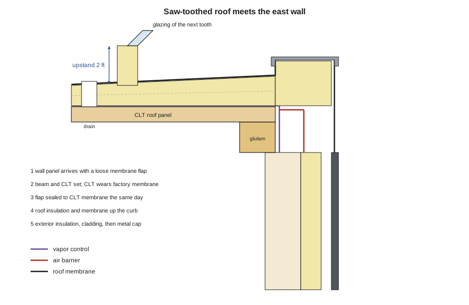
The saw-tooth glazing rises from the valley on an insulated upstand at least as high as the drift that the snow load calculation expects, about 2 feet in this valley. The roof membrane runs up the upstand and under the glazing system's sill, where it is sealed to the glazing's own membrane. The valley drains to two internal drains, one near each end, so that one blocked drain does not flood the valley, and the drain bodies are inside the insulation so that they do not freeze. Overflow scuppers through the parapet carry water out if both drains block. Ortega adds a heat trace cable in the valley gutter for the first winters, until the facilities staff learn how the roof behaves, and a walkway pad along the valley so that whoever clears the snow does not damage the membrane.
The order of installation, written as numbered notes on the detail, is the part Vasić cares about most. One: the wall panel arrives with its air barrier membrane lapped onto a loose flap at the top. Two: the glulam beam and the CLT roof panel are lifted into place, the roof panel already wearing its membrane. Three: the wall's flap is turned up and sealed to the roof membrane's lap, closing the air barrier the same day, from a lift outside the wall. Four: the roof insulation and membrane are installed. Five: the exterior insulation and cladding of the wall go up, and last of all the metal cap. If the steps happen in a different order, the detail will not work, and the drawing says so.
Checking for condensation
A detail must also be checked for heat and moisture. Vasić asks the class to calculate the temperature at each layer of the avenue wall on a design winter night, and to compare it with the dew point of the indoor air, the temperature at which water vapor from the room would condense. The script below does it by the steady-state method the students learned in the environmental systems course: the temperature falls across each layer in proportion to its share of the total thermal resistance.
import math
# Temperature at each layer of the avenue wall on a design winter night, against the indoor dew point
t_in, t_out, rh = 70, -14, 0.35          # indoor and outdoor temperature (F), indoor relative humidity
layers = [("inside air film", 0.68), ("gypsum board", 0.45), ("smart retarder", 0.0), ("stud cavity insulation", 22.0),
          ("plywood sheathing", 0.62), ("exterior mineral wool", 13.6), ("cavity and cladding", 0.85), ("outside air film", 0.17)]
def dew_point(t_c, rh):
    a, b = 17.62, 243.12
    g = math.log(rh) + a * t_c / (b + t_c)
    return b * g / (a - g)
tin_c = (t_in - 32) / 1.8
dp = (lambda c: c * 1.8 + 32)(dew_point(tin_c, rh))
total = sum(r for _, r in layers)
t = t_in
print(f"indoor dew point {dp:.1f} F; total resistance {total:.2f} h ft2 F/Btu")
for name, r in layers:
    t -= (t_in - t_out) * r / total
    flag = "  below dew point" if t < dp else ""
print(f"after {name:<24} {t:6.1f} F{flag}")indoor dew point 41.1 F; total resistance 38.37 h ft2 F/Btu after inside air film 68.5 F after gypsum board 67.5 F after smart retarder 67.5 F after stud cavity insulation 19.4 F below dew point after plywood sheathing 18.0 F below dew point after exterior mineral wool -11.8 F below dew point after cavity and cladding -13.6 F below dew point after outside air film -14.0 F below dew point
The result confirms what the class found for the community hub: on a design night, the sheathing is far below the dew point of indoor air at 70 °F and 35% relative humidity. The wall is safe only because the smart vapor retarder on the warm side of the cavity, and the continuous air barrier, keep the indoor moisture from reaching the cold sheathing. Vasić asks Callum what would happen if the exterior insulation were thicker. More of the wall's resistance would lie outside the sheathing, the sheathing would be warmer, and the wall would be more tolerant of a small leak in the retarder. With all the insulation outside the sheathing, as in the roof, the sheathing would stay above the dew point all winter and could serve as the vapor control layer itself. Callum keeps the wall as designed, because it fits the prefabricated panels, but he adds a note to the detail that the retarder must be continuous and inspected before the gypsum board goes on, and he asks the city to keep the building's winter humidity below 35%.
The window sill
The window sill is where the most water arrives and the most mistakes are made. Callum's sill detail shows the prefabricated wall panel with a rough opening lined, in the factory, with a membrane that wraps from the air barrier on the face of the sheathing into the opening. A sloped sill pan, with end dams that turn up at each side, sits under the window, so that any water that gets past the window's own seals runs out to the face of the wall rather than into it. The window sits in line with the insulation, on shims at its support points, with an air seal all round between the frame and the membrane lining. Outside, a metal sill flashing slopes away from the window and projects 1½ inches beyond the cladding, with a drip on its underside and turned-up ends that stop water running off the corners and down the cladding behind.
Petrenko asks to see the brick at the sill on the avenue wall. Brick is porous; rain soaks into it and runs down inside it, and the cavity behind it must drain. At every window head in the brick, a steel angle carries the brick above, and a flashing under the angle directs water in the cavity out through weep holes. At every sill, the brick below is protected by the metal sill flashing, or by a sloped brick sill laid on a flashing with weeps below. He points out that Callum's drawing shows the angle bolted directly to the wall panel, through the exterior insulation, which would be a thermal bridge along the whole width of each window. Ortega suggests carrying the angle on stand-off brackets, which pass through the insulation at a few points rather than along a line.
The base of the wall
At the base of the avenue wall, the brick sits on a flashing over the concrete grade beam, with weeps above the flashing that drain the cavity to the outside at least 6 inches above the sidewalk. The air barrier on the wall panel is lapped onto the grade beam and sealed, and the exterior insulation continues down the outside of the grade beam to below the frost line, protected by a board where it is exposed above grade. The floor slab's edge is separated from the grade beam by insulation, so that the slab edge does not become a cold line along the base of every wall. On the park side, where snow will lie against the wall, the larch cladding stops 12 inches above the terrace, the wall below is concrete with a protective board, and the terrace slopes away from the building.
Vasić asks about the larch boards. Larch is durable and needs no finish, but it will move with moisture, more across the grain than along it, and the boards must be fixed to allow it. Their ends must be cut so that water drains off them, not into them, and they must be held off the wall by battens that leave a ventilated gap. The fixings must be stainless steel, because the tannins in larch will stain and corrode ordinary steel. And the boards on the south will weather faster and turn silver sooner than those in the shadow of the multipurpose wing, which Callum should accept as part of the building's character rather than fight with stains.
Tolerances, movement and maintenance
Real construction is not as precise as a drawing. Concrete grade beams may be ¾ inch out of line; glulam columns may be a fraction of an inch out of plumb; prefabricated wall panels have tight tolerances of their own but must meet a structure that does not. Every junction between trades needs room for these differences: shims and slotted connections where the wall panels meet the structure, adjustable clips for the cladding, sealant joints sized for the expected movement plus the tolerance. Timber and concrete also move differently over time. The CLT roof and floors will shrink slightly as they dry in the first heating seasons; the concrete cores will not. Where a timber floor meets a concrete core, the connection must allow the timber to move, or the floors will crack the finishes at every core wall.
Maintenance is the last question Vasić asks of every detail. Where the roof drain can be cleaned, where the sealant joints can be reached to be renewed in twenty years, where a broken pane of the saw-tooth glazing can be replaced from the roof without scaffolding, where the larch boards can be removed one at a time. A detail that cannot be maintained will fail eventually, and when it fails it will be repaired badly, by someone in a hurry. Callum adds a roof anchor system for fall protection along the valleys, a removable cover on the overflow scuppers, and a note on the glazing details that the outer panes are replaceable from outside.
Worked problem
A sill that leaks
Ortega shows the class a photograph from a recently completed library: water stains on the inside face of a wall below a window, every spring. The window was set on a flat sill with the membrane turned into the opening but no sill pan. What went wrong, and how does Callum's detail prevent it?
Show solution
- Identify the source: water that passes the window's own seals, which all windows eventually allow, collects on a flat sill.
- Follow it: with no slope and no end dams, the water runs to the ends of the sill and into the wall at the corners of the opening.
- Note the timing: the stains appear in spring, when snow lying on the sill melts and refreezes for weeks.
- Check Callum's detail: a sloped sill pan with end dams collects the water and drains it out to the face of the wall above the metal sill flashing.
- Check the order: the pan must be installed and sealed to the opening's membrane before the window goes in, and inspected before it is covered.
Answer: A sloped, end-dammed sill pan, installed and inspected before the window, drains the water that the window's seals let past.
Exercise 10: detailing
- Draw three details of your building at 3 inches to the foot: the roof-wall junction, a window sill and the base of the wall.
- Trace each control layer continuously through each detail, and number the steps of installation.
- Check your wall for condensation with the script, and state what keeps indoor moisture from the cold layers.
- Add notes on tolerances, movement and maintenance to each detail.
Self-check
- Where does the water go in every detail, including the water that gets past the first line of defense?
- Could the detail be built in the order you have numbered, by people standing somewhere safe?
- How will each junction be inspected, maintained and repaired?
Common mistakes
MistakeDrawing a detail that looks right without an order of installation.
InsteadNumber the steps and check that each layer can be installed and sealed when it needs to be.
MistakeRelying on sealant alone to keep water out.
InsteadUse slopes, laps, flashings and drainage; treat sealant as a secondary line.
MistakeSetting windows on flat sills without pans.
InsteadUse sloped sill pans with end dams that drain to the face of the wall.
MistakeFixing shelf angles and canopies straight through the insulation.
InsteadUse stand-off brackets and point connections.
MistakeIgnoring the different movements of timber and concrete.
InsteadAllow for shrinkage of the timber where it meets the concrete cores.
Summary and key terms
- A detail shows how parts meet and how the junction performs: materials, order of installation, continuity of control layers, drainage, movement and maintenance.
- Callum's roof-wall junction laps factory-applied membranes on the CLT and wall panels and closes the air barrier on the day the roof panel is set.
- The saw-tooth glazing rises above the expected drift, and the valleys drain to two internal drains with overflows.
- On a design night the sheathing is below the dew point of indoor air; the continuous smart vapor retarder and air barrier keep the wall safe.
- Sills, shelf angles, the base of the wall and the larch cladding each follow the principles of drainage, laps, ventilation and room to move.
- Detail
- A large-scale drawing of a junction between parts of a building, showing how it is built and how it performs.
- Sill pan
- A sloped, waterproof tray under a window that drains water that passes the window's seals.
- End dam
- A turned-up end of a flashing or sill pan that stops water running off its ends into the wall.
- Shelf angle
- A steel angle that supports brick cladding over an opening or at a floor.
- Tolerance
- The permitted difference between the drawn and the built position or size of a part.
Practice problems
Work each problem on paper first, then reveal the answer to check.
A wall has a total resistance of R-38.4 and a cavity insulation of R-22. Indoors is 70 °F and outdoors −14 °F. How much does the temperature drop across the cavity insulation?
Show answer
84 × 22 ÷ 38.4 ≈ 48 °F.
What is the dew point of air at 70 °F and 35% relative humidity?
Show answer
About 41 °F.
Why is the wall safe although its sheathing is colder than that?
Show answer
The continuous vapor retarder and air barrier on the warm side keep indoor moisture from reaching the sheathing.
Why should a valley have two drains?
Show answer
So that one blocked drain does not flood the valley; overflows handle the case where both block.
What fixings should be used with larch cladding, and why?
Show answer
Stainless steel, because tannins in larch stain and corrode ordinary steel.
Why must a timber floor connection to a concrete core allow movement?
Show answer
The timber shrinks as it dries and the concrete does not.
Lesson quiz · 5 questions
Score 60% or more to complete this lesson.
Create a free account to save your progress, take quizzes and earn a certificate.