
ARCH-301 · Lesson 11 of 12 · 23 min
Technical documentation
In week eleven Hartmann clears the long studio wall and asks each student to pin up their whole building as a set of drawings, in order, as if they were handing it to a builder. Callum has drawn a great deal over ten weeks, but it has been drawn for the studio's reviews, one system at a time: massing models for the schematic review, a grid for Szymańska, wall sections for Ortega, a zoning plan for Mensah, a code plan for Kostyshyn, route plans for Achterberg, charts for Sethi and Takahashi, details for Vasić. Pinned in order, the sheets contradict each other. The wall sections show the upper floor at 15¾ feet; one building section still shows 14 feet. The east stair has moved on the plans but not on the code plan. The roof monitor over the library appears on the reflected ceiling plan and nowhere else. Ben Okafor, the cost estimator who priced the mixed-use building in the urban studio, is walking down the wall with a pad of notes. 'I can price any one of these,' he says. 'I cannot price all of them at once.'
What documentation is for
Technical documentation is the description of a building complete enough for others to price it, approve it and build it. In practice it is a set of drawings, a project manual of specifications, and increasingly a coordinated building information model, produced in stages from schematic design through design development to construction documents. The studio stops at the end of design development, the stage at which every system is defined, sized and coordinated, and a few parts are detailed, but the drawings are not yet complete enough for construction. What Hartmann asks for this week is the discipline of documentation: a set that is organized, consistent, cross-referenced and complete for its stage, so that a reader can find any piece of information once and trust it.
She reminds the class that the documents have several readers, each with their own questions. The client wants to know that the building matches the brief. The plans examiner wants to see the code analysis and the plans, sections and details that show compliance. The cost estimator wants quantities and qualities: how much of each thing, and of what kind. The builder wants to know what to build, where and in what order. The engineers want to see their systems coordinated with everyone else's. And in twenty years, the city's facilities staff will want to know what is behind a wall before they open it. Each reader must be able to find their answer without reading everything else.
Organizing the drawing set
Drawing sets are organized by discipline, with a letter prefix, and within each discipline by type of drawing, with a number. The United States National CAD Standard sets the usual conventions: G for general, C for civil, L for landscape, A for architectural, S for structural, M for mechanical, P for plumbing, E for electrical and FP for fire protection, with sheet numbers that group plans in the 100s, elevations in the 200s, sections in the 300s, large-scale sections in the 400s, details in the 500s and schedules in the 600s. Every drawing on a sheet has a number and a title, and every reference to another drawing, a section mark on a plan or a detail tag on a section, gives the drawing's number and the sheet it is on. A reader who sees a detail tag on the wall section must be able to turn to the detail without searching.
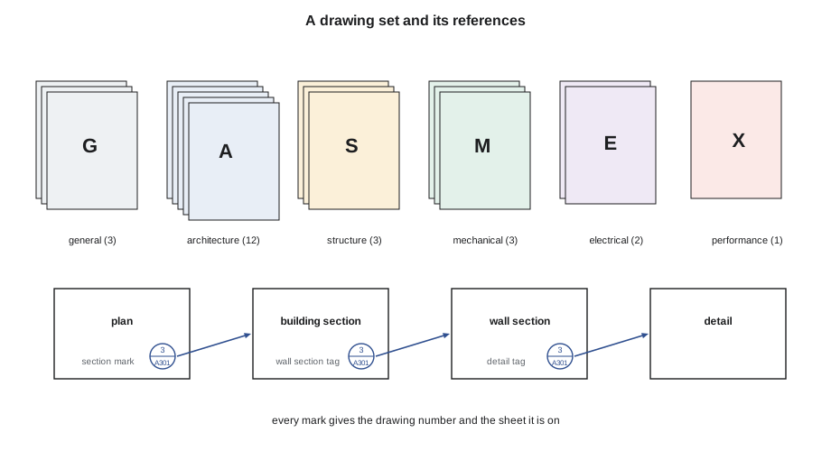
The studio's set is smaller than a real one, but it must have the same structure. The script below lists Callum's sheets by discipline and checks that every system the review panel will ask about has at least one sheet that provides its evidence.
# The studio drawing set: sheets by discipline and a check that every system has its evidence
sheets = {
    "G general":      ["cover and sheet index", "code analysis and code plans", "accessibility plans"],
    "A architecture": ["site plan", "ground floor plan", "upper floor plan", "roof plan", "reflected ceiling plans",
                       "elevations", "building sections", "wall sections", "details: roof and parapet",
                       "details: windows and saw-teeth", "details: base of wall and terrace", "door and window schedules"],
    "S structure":    ["foundation plan", "framing plans", "core and brace elevations"],
    "M mechanical":   ["thermal zones and equipment", "ventilation and shafts", "coordination sections"],
    "E electrical":   ["power and refuge circuits", "lighting and controls"],
    "X performance":  ["energy and carbon summary"],
}
total = sum(len(v) for v in sheets.values())
for disc, names in sheets.items():
    print(f"{disc:<15} {len(names):2d} sheet" + ("s" if len(names) > 1 else ""))
print(f"total {total} sheets")
evidence = {"structure": "S", "envelope": "wall sections", "mechanical": "M", "code": "code analysis",
            "access": "accessibility", "energy": "energy", "carbon": "carbon", "details": "details"}
listing = " | ".join(d + " " + " ".join(n) for d, n in sheets.items())
missing = [k for k, key in evidence.items() if key not in listing]
print("evidence missing for:", ", ".join(missing) if missing else "nothing")G general 3 sheets A architecture 12 sheets S structure 3 sheets M mechanical 3 sheets E electrical 2 sheets X performance 1 sheet total 24 sheets evidence missing for: nothing
Twenty-four sheets is a reasonable size for a comprehensive studio project at the end of design development. A real set for a building of this size at the same stage might have twice as many, and the construction documents three or four times as many. Hartmann asks for a sheet index on the cover, a title block on every sheet with the project, the sheet's number and title, the date and a revision record, and a north arrow and a scale on every plan.
Consistency and coordination
The contradictions on Callum's wall are normal at this stage and dangerous at the next. A builder who finds two floor-to-floor heights on two drawings will either ask, which costs time, or choose one, which may be the wrong one. The usual remedy in practice is a single building information model from which plans, sections and elevations are all drawn, so that a change in one place changes every drawing. A model reduces contradictions between views, but not between the model and the engineers' models, or between the drawings and the specifications, or between what was drawn and what was meant. Coordination remains a human task: a weekly review of the overlapping drawings of every discipline, a clash report run on the combined models, and a person whose job is to check.
Hartmann gives the students a short checklist to run before the final review. Are the grid lines and their names the same on every architectural, structural and mechanical drawing? Are floor levels and heights the same on every section and elevation? Does every section mark, detail tag and elevation mark point to a drawing that exists and shows what the mark promises? Is every room named and numbered the same way on plans, schedules and the code plan? Is every wall type on the plans defined on a wall type sheet? Do the door and window schedules match the plans? Does the code analysis describe the building as drawn, not as it was three weeks ago? Callum finds nineteen errors and fixes all but two before the end of the week.
Schedules and specifications
Some information is better in a table than on a drawing. Schedules list the doors, windows, room finishes, equipment and fixtures, each with a mark that appears on the plans. The door schedule of the Commons, for example, gives each door's size, material, fire rating, hardware set, power operator if any, and whether it is on the accessible route; it is where Kostyshyn's fire separations and Achterberg's door clearances meet. A wall type sheet defines each wall by its layers, its thermal value, its fire rating and its acoustic rating, so that the plans need only show a tag.
Specifications describe the qualities of materials and the standards of workmanship that drawings cannot show: the grade of glulam, the species and moisture content of the larch, the airtightness target and how it will be tested, the procedures for protecting the timber from rain during construction, the mock-ups and inspections required before the work is covered. In North America they are usually organized by MasterFormat, whose divisions run from general requirements in Division 01 to wood in Division 06, thermal and moisture protection in 07, openings in 08, fire suppression in 21, plumbing in 22, mechanical in 23 and electrical in 26. American offices often start from a commercial master specification that follows the same divisions. At the end of design development, the studio asks for an outline specification: a few lines for each main system, naming the products, the standards and the performance requirements.
Callum's outline specification for the mass timber structure shows how much information belongs in words. It names the glulam stress grade and the CLT grade and thickness; it requires the members to be fabricated to shop drawings from a model coordinated with the mechanical and sprinkler layouts, so that holes for ducts are cut in the factory, not on site; it requires the timber to be delivered wrapped, stored off the ground and covered, and installed with the roof membranes applied in the factory; it sets a maximum moisture content at enclosure; and it requires an independent inspection of the connections before they are concealed. None of this could be drawn, and every part of it decides whether the exposed timber the library wants will look as intended.
Cost
The brief's construction budget is tested this week, because only now are there enough quantities to estimate. Okafor prepares an elemental cost plan, which groups costs by building element rather than by trade: substructure, structure, envelope, interiors, mechanical, electrical, fire protection, elevators and site work. Elemental plans are useful in design because each element can be compared with similar buildings, and the effect of a design decision can be traced to the element it changes. The script below sets out his plan for Callum's building, adds a design contingency and compares the result with the budget, then applies the savings Callum proposes.
# Elemental cost plan of the Commons at the end of design development, against the budget
area = 40400                                         # gross floor area (ft2)
rates = {"substructure": 35, "structure": 67, "envelope": 98, "interiors": 48,
         "mechanical": 72, "electrical": 35, "fire protection": 6, "elevators": 6, "site work": 21}
subtotal = sum(rates.values())
contingency = 0.05                                    # design contingency at this stage
cost = subtotal * (1 + contingency)
budget = 400                                     # dollars per ft2 including site work
print(f"elements {subtotal:,.0f}, with contingency {cost:,.0f} dollars per ft2 against {budget:,}")
print(f"total {cost * area / 1e6:,.2f} million against {budget * area / 1e6:,.2f} million: "
      f"{'over' if cost > budget else 'under'} by {abs(cost / budget - 1):.1%}")
savings = {"six saw-teeth instead of eight": 5, "gypsum topping instead of concrete": 2.5,
           "standard sizes for the larch boards": 1.5, "one fewer roof drain line by regrading": 1}
for name, s in savings.items():
    cost -= s * (1 + contingency)
    print(f"  {name:<40} saves {s:g} -> {cost:,.0f}")
print(f"after the savings: {cost:,.0f} per ft2, {'within' if cost <= budget else 'still over'} the budget")elements 388, with contingency 407 dollars per ft2 against 400 total 16.46 million against 16.16 million: over by 1.9% six saw-teeth instead of eight saves 5 -> 402 gypsum topping instead of concrete saves 2.5 -> 400 standard sizes for the larch boards saves 1.5 -> 398 one fewer roof drain line by regrading saves 1 -> 397 after the savings: 397 per ft2, within the budget
Callum's building is about 2% over the budget at the end of design development, which Okafor says is a good result; many projects at this stage are 10% over. The largest elements are the envelope, with its saw-toothed roof and triple glazing, the mechanical systems, with the borefield, and the structure. Callum proposes four savings. Reducing the saw-teeth from eight to six, with each one slightly larger, keeps the daylight in the makerspace and upper floor and removes two valleys, two sets of drains and a good deal of glazing frame. A gypsum-based topping instead of concrete on the upper floor saves cost and carbon; Szymańska's vibration check and the acoustician's review accept it for the classroom floor, provided the library's study rooms below get extra absorption in their ceilings. Standard lengths for the larch boards, and regrading the roof to remove one line of drains, complete the savings and bring the building inside the budget. Okafor warns that the contingency will be needed: the borefield's cost depends on the test bore, and the price of timber has moved a great deal in recent years.
Worked problem
Finding a contradiction
During the final check, Callum finds that the wall type sheet defines the avenue wall with 4 inches of exterior insulation, while the energy summary was calculated with 6 inches. Which is right, and what must change?
Show solution
- Trace the history: the envelope lesson used 4 inches; Sethi's sensitivity runs tested 6 inches; the summary was updated, the wall type was not.
- Decide the design: the energy target is met with either, but the margin is larger with the thicker insulation, and the dew-point check showed that thicker exterior insulation makes the wall more tolerant.
- Check the consequences: thicker insulation changes the wall thickness, the window depth, the clip length, the brick ties, the shelf angle brackets and the cost.
- Choose: 6 inches, because it improves both the energy margin and the wall's moisture performance, and update every drawing and the cost plan.
- Record the change in the revision block of every affected sheet.
Answer: The thicker insulation is adopted, the wall type, wall sections, details, energy summary and cost plan are all updated, and the revision is recorded.
Exercise 11: technical documentation
- Organize your drawings into a set by discipline with a sheet index, title blocks and consistent numbering.
- Run Hartmann's coordination checklist and list every contradiction you find and how you resolved it.
- Prepare a door schedule, a wall type sheet and an outline specification for your structure and envelope.
- Prepare an elemental cost estimate with a contingency and compare it with the budget; propose savings if needed.
Self-check
- Does every mark on every drawing point to a drawing that exists?
- Does your code analysis describe the building as drawn now?
- Can a cost estimator find a quantity and a quality for every major element?
Common mistakes
MistakePinning up drawings made for separate reviews as if they were a set.
InsteadOrganize, cross-reference and check them for consistency.
MistakeAssuming a model removes all contradictions.
InsteadCoordinate the models of all disciplines and the specifications, and check them by hand.
MistakePutting on drawings what belongs in specifications.
InsteadDescribe qualities, standards, protection, mock-ups and inspections in words.
MistakeEstimating cost only at the end of the documents.
InsteadEstimate at each stage by elements, while there is still time to change the design.
MistakeSpending the contingency on design changes.
InsteadKeep it for the risks that remain, such as ground conditions and price changes.
Summary and key terms
- Technical documentation describes a building completely enough for its stage to be priced, approved and built.
- Drawing sets are organized by discipline and drawing type, and every reference gives the drawing and sheet it points to.
- A model reduces contradictions between views, but coordination across disciplines and documents remains a human task.
- Schedules and specifications carry information that drawings cannot: sizes, ratings, hardware, qualities, standards, protection and inspection.
- Callum's elemental cost plan was about 2% over budget; four savings brought it inside, with the contingency kept for remaining risks.
- Design development
- The design stage in which every system is defined, sized and coordinated before construction documents.
- Construction documents
- The drawings and specifications from which a building is priced, approved and built.
- Specification
- A written description of the materials, products, standards and workmanship required.
- Elemental cost plan
- A cost estimate organized by building element, such as structure or envelope.
- Contingency
- An allowance in a cost estimate for risks and changes not yet known.
Practice problems
Work each problem on paper first, then reveal the answer to check.
A building of 40,400 square feet is estimated at 407 dollars per square foot. What is its total cost?
Show answer
About 16.4 million dollars.
The budget is 400 dollars per square foot. By how much is the estimate over?
Show answer
About 1.9%.
What is the difference between an elemental cost plan and a trade breakdown?
Show answer
An elemental plan groups costs by building element; a trade breakdown groups them by who does the work.
Where do the fire rating and hardware of each door belong?
Show answer
In the door schedule, keyed to the plans.
Why should holes for ducts in glulam beams be specified to be cut in the factory?
Show answer
So they are placed where the engineer allows, coordinated with the model, and not cut on site.
What is a sheet index for?
Show answer
To list every sheet with its number and title, so readers can find any drawing.
Lesson quiz · 5 questions
Score 60% or more to complete this lesson.
Create a free account to save your progress, take quizzes and earn a certificate.