
APP-110 · Lesson 7 of 12 · 25 min
Service manuals, tech sheets and wiring diagrams
▶ Video coming soon A video version of this lesson is on the way.
On Tuesday, October 27, Kiran spent the first call of the day on his back in front of an electric dryer that ran but did not heat, holding a folded sheet of paper that Dee had pulled from behind the dryer's control console. The sheet was printed on both sides in small type: a wiring diagram, a schematic, a table of component resistances, a chart of the timer sequence and a list of test points. "This is the tech sheet," Dee said. "Every appliance has one or the information is online. It's the map. If you don't read the map, you're just guessing with a meter in your hand."
No technician can remember the wiring, the test values and the diagnostic codes for every model of every brand. Manufacturers provide service information so that technicians can find faults quickly and fix them safely. This lesson describes the kinds of service information, how to find and read a tech sheet, the difference between a wiring diagram and a schematic, and how diagnostic modes and fault codes help. Reading schematics to trace faults is covered in depth in APP-120.
Kinds of service information
Several documents come with or apply to every appliance:
- The installation instructions: how to install the appliance, its clearances, its electrical, water, gas and venting requirements. These are the manufacturer's instructions that codes and warranties refer to.
- The use and care guide (owner's manual): how the customer operates and maintains the appliance, and a basic troubleshooting list. Many service calls are answered by it.
- The tech sheet: a short technical summary, usually packed inside the appliance, with the wiring diagram, schematic, component values and test procedures.
- The service manual: the full repair guide for a model or a family of models, with disassembly steps, theory of operation, diagnostic flowcharts and specifications. Manufacturers usually provide it to authorized servicers or through paid subscriptions.
- The parts list and exploded views: drawings that show every part with its number, used to identify and order parts.
- Service bulletins: notices about known problems, updated parts and new procedures (lesson 6).
Penfold's authorized-servicer accounts give its technicians access to the service manuals, bulletins and parts systems of three brands through online portals on their tablets. For other brands, technicians rely on the tech sheet in the appliance, the manufacturer's public support pages, parts suppliers' diagrams and, sometimes, a call to a manufacturer's technical support line.
Finding the tech sheet
The tech sheet is usually in the appliance, in a plastic sleeve or folded in a pocket, so it stays with the machine for its whole life. Typical places are:
| Appliance | Typical tech sheet locations |
|---|---|
| Refrigerator | Behind the kick plate at the bottom front; in a pocket on the back; under the top hinge cover |
| Range | Behind the control panel; under the cooktop; on the back panel |
| Dishwasher | Behind the lower access panel or kick plate; inside the door |
| Washer | Under the control console; inside the cabinet at the back; on the back panel |
| Dryer | Behind the control console; inside the front or back panel |
Dee's rule is to read the tech sheet before testing anything, even on a model she knows well, because manufacturers change parts and values over a model's life. And she always puts it back exactly where she found it.
Wiring diagrams and schematics
Tech sheets usually show the electrical circuits in two ways, and they serve different purposes:
- A wiring diagram shows the parts roughly where they are in the appliance, with the actual wires between them, their colors and the connectors and terminals they plug into. It answers the question: where is this wire, and what does it plug into?
- A schematic, often drawn as a ladder diagram, shows how the circuits work, not where the parts are. The two supply lines run down the sides like the rails of a ladder, and each rung is one circuit: a load, such as a heater or a motor, with the switches and controls that turn it on and off in series with it. It answers the question: what has to happen for this load to get power?
A technician uses the schematic to work out which parts could stop a load from working, then the wiring diagram to find those parts and their wires in the appliance.
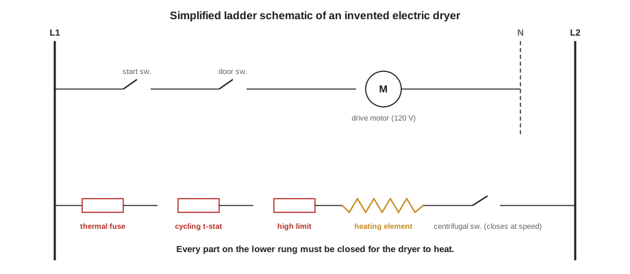
Common schematic symbols include:
| Symbol | Part |
|---|---|
| Zigzag line or rectangle | Resistor or heating element |
| Circle with M | Motor |
| Coil (loops) with a line | Solenoid, valve coil or relay coil |
| Contact with a gap (normally open) | Switch or relay contact that closes when operated |
| Contact closed with a line through it (normally closed) | Switch or contact that opens when operated |
| Contact with a bimetal or temperature mark | Thermostat or thermal limit |
| Fuse symbol (line in a box or S-curve) | Thermal fuse or fuse |
| Three descending lines | Ground connection |
Wires are identified by color, usually abbreviated: BK black, WH white, RD red, BU blue, OR orange, YL yellow, GN green, GY gray, VT violet, PK pink, BR brown. A striped wire is shown with two codes, such as WH/BK for white with a black stripe. Connectors are named on the diagram, such as P3 or J5, and each pin has a number, so P3-2 means pin 2 of connector P3.
Reading a circuit: the dryer that would not heat
Back at the dryer, Kiran traced the heater rung on the schematic with his finger. For the element to heat, current had to flow from L1 through the thermal fuse, the cycling thermostat, the high limit thermostat, the element, and the centrifugal switch on the motor, which closes only when the motor is running at speed, to L2. If any one of those five parts was open, the dryer would run but not heat.
Worked problem
Finding the open part
With the dryer unplugged, Kiran disconnects each part on the heater rung in turn and measures it. The tech sheet gives these values: thermal fuse closed (about 0 Ω), cycling thermostat closed when cold (about 0 Ω), high limit closed when cold (about 0 Ω), element about 10 to 12 Ω, centrifugal switch contacts open with the motor stopped. His readings: thermal fuse OL, cycling thermostat 0.2 Ω, high limit 0.1 Ω, element 10.9 Ω. Which part has failed, and what should he check next?
Show solution
- Compare each reading with the tech sheet.
- Thermal fuse: OL, but it should be about 0 Ω, so it is open.
- Cycling thermostat, high limit and element are all normal.
- The centrifugal switch cannot be checked with the motor stopped, but the dryer tumbles normally and the open fuse already explains the fault.
Answer: The thermal fuse is open. A thermal fuse opens because the dryer overheated, most often because the vent is blocked or too long. Replacing the fuse without checking the vent means it will blow again. The next step is to check the vent (lesson 9).
Dee pulled the dryer out, disconnected the vent and found the duct behind it crushed flat and packed with lint. Kiran replaced the thermal fuse and Dee replaced the crushed foil duct with a rigid metal one; they measured the airflow at the outside hood and showed the customer the lint. Kiran wrote in his notebook: a blown thermal fuse is a symptom, not a cause.
Component values and charts
Most tech sheets include a table of component values: the resistance of each heater, motor winding, valve coil and sensor, and the temperatures at which thermostats open and close. Temperature sensors called thermistors have a resistance that changes with temperature, and the tech sheet gives a table of resistance against temperature. A technician measures the sensor and compares the reading with the table at the actual temperature.
Worked problem
Checking a thermistor
A refrigerator's tech sheet gives its freezer thermistor as 16.2 kΩ at 0 °F and 10.0 kΩ at 23 °F. Kiran disconnects the sensor in a freezer that is at 0 °F and reads 16.0 kΩ. Is the sensor good?
Show solution
- Expected at 0 °F: 16.2 kΩ.
- Difference: 16.2 − 16.0 = 0.2 kΩ, about 1 in 100 of the expected value.
Answer: The sensor is good; a small difference is normal. A thermistor that read OL or close to 0 Ω, or a value matching a very different temperature, would be faulty.
Older electromechanical washers, dryers and dishwashers have timer charts that show which timer contacts close at each point in the cycle. Newer appliances with control boards replace the timer chart with a list of the board's outputs and a diagnostic mode.
Diagnostic modes and fault codes
Most appliances made in the last fifteen years have an electronic control board that watches its own sensors and loads. When it detects a problem, such as a drain that takes too long, a heater that does not warm the water, or a door lock that does not confirm, it stores a fault code and often shows it on the display. Most boards also have a service or diagnostic mode, entered by a key sequence printed on the tech sheet, that lets the technician:
- read the stored fault codes, often with the most recent first;
- run each load, such as the pump, valves, motor, heater and door lock, one at a time to see whether it works;
- read sensor values, such as water level, temperature and motor speed;
- clear the fault history after the repair.
A fault code points to where a problem was detected, not necessarily to the failed part. A code for a long drain time can mean a failed pump, but also a blocked drain hose, a kinked standpipe connection or a clogged filter. The tech sheet's fault code table usually lists the possible causes and the checks to make in order.
Worked problem
Reading a fault code
A dishwasher shows an invented code F21, which its tech sheet defines as drain time over 6 minutes. In service mode, Kiran runs the drain pump and hears it hum but sees almost no water leave the tub. The pump's winding reads 18 Ω against a tech sheet value of 15 to 20 Ω. What should he check next?
Show solution
- The code means water drained too slowly.
- The pump is getting power (it hums) and its winding is normal.
- So the fault is probably mechanical: a blockage in the pump inlet or impeller, the filter, or the drain hose and air gap.
Answer: Check the filter, the pump impeller for debris such as glass, and the drain hose path. Replacing the pump without checking would likely waste a part. This was the blocked drain from Kiran's first day.
Diagnostic modes can run loads with panels off, and some run heaters and pumps at full power. Follow the tech sheet's safety notes, keep hands away from live terminals and moving parts, and exit service mode before you leave.
Your own notes, photos and support lines
Service information is not only what the manufacturer prints. Experienced technicians keep their own records: photographs of wiring before disassembly, notes on unusual faults and how they were found, test values they have measured on good parts, and tips from other technicians. Dee's phone has hundreds of photos organized by brand and model family, and her notebook from her first year is still in her van. Kiran started his own the same way.
When the documents run out, manufacturers' technical support lines help. Authorized servicers can call a support line staffed by experienced technicians who know the brand's common faults, can walk through a diagnostic procedure and can authorize warranty parts. Before calling, have the model and serial number, the fault codes, the readings you have taken and what you have already checked; support technicians expect a caller to have done the basic tests. Online technician forums and parts suppliers' repair guides can also help, but treat them with care: advice there may be for a different model or simply wrong, and nothing on a forum replaces the manufacturer's safety instructions.
Whatever the source, the rule is the same: confirm a value or a procedure against the manufacturer's information for that exact model before acting on it.
Common mistakes
MistakeStarting tests before reading the tech sheet.
InsteadRead the tech sheet first; values and wiring change over a model's life.
MistakeUsing the wiring diagram to work out why a load does not run.
InsteadUse the schematic to find what must be closed; use the wiring diagram to find it.
MistakeReplacing a blown thermal fuse without finding the cause.
InsteadFind the overheating cause, usually a blocked or long vent, before replacing the fuse.
MistakeTreating a fault code as the name of the failed part.
InsteadA code shows where a problem was detected; follow the tech sheet's causes and checks.
MistakeLeaving the appliance in service mode or the tech sheet out.
InsteadExit service mode and return the tech sheet to its pocket.
Summary and key terms
- Service information includes installation instructions, use and care guides, tech sheets, service manuals, parts lists and bulletins.
- The tech sheet is usually inside the appliance; read it first and put it back.
- A wiring diagram shows where parts and wires are; a ladder schematic shows how each circuit works.
- Every switch in series with a load must be closed for the load to run; isolate and measure each one.
- Compare readings with the tech sheet values, including thermistor tables.
- Fault codes and service modes point to where to look; they do not name the failed part on their own.
- Tech sheet
- A short technical summary packed with an appliance, with its wiring, values and test procedures.
- Service manual
- The full repair guide for a model or family of models.
- Wiring diagram
- A drawing showing the physical location of parts and the wires, colors and connectors between them.
- Schematic
- A drawing showing how the circuits work; in a ladder schematic each rung is one circuit.
- Thermistor
- A temperature sensor whose resistance changes with temperature.
- Thermal fuse
- A one-time safety device that opens if a part overheats.
- Fault code
- A code stored by a control board when it detects a problem.
- Service mode
- A diagnostic mode, entered by a key sequence, for reading codes and testing loads.
Practice problems
Work each problem on paper first, then reveal the answer to check.
Name four kinds of service information.
Show answer
Installation instructions, use and care guide, tech sheet, service manual, parts list, bulletins.
What question does a wiring diagram answer?
Show answer
Where a part or wire is and what it connects to.
What does P3-2 mean on a diagram?
Show answer
Pin 2 of connector P3.
Why does a thermal fuse usually open in a dryer?
Show answer
The dryer overheated, most often because of a blocked or long vent.
What does a fault code tell you?
Show answer
Where the board detected a problem, with possible causes listed in the tech sheet.
Lesson quiz · 5 questions
Score 60% or more to complete this lesson.
Create a free account to save your progress, take quizzes and earn a certificate.