
AI-450 · Lesson 2 of 12 · 24 min
Coordinate frames, transforms and forward kinematics
A robot must constantly answer questions about geometry. Where is the gripper relative to the table? Where is the object the camera just detected, in the coordinates the arm understands? Which way is the mobile base facing on the map? Every sensor, link and object has its own coordinate frame, and the robot needs to convert positions and orientations between them quickly and correctly. Mistakes in frames, such as a sign error, a swapped axis or a transform applied in the wrong order, are among the most common bugs in robotics and can send an arm crashing into a table. This lesson develops the mathematics of rigid-body transforms: rotation matrices, Euler angles and their pitfalls, quaternions, homogeneous transforms and their composition, and then applies them to forward kinematics, the calculation of where a robot's tool is from its joint angles. It also introduces joint types, degrees of freedom, the Denavit-Hartenberg convention and robot description files.
Frames and rigid-body motion
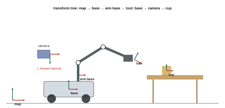
A coordinate frame is an origin plus three perpendicular axes. Robots use many frames: a world or map frame, the robot base frame, a frame for each link, sensor frames for cameras and lidars, a tool frame at the gripper, and frames attached to detected objects. A rigid body's pose (position and orientation) relative to another frame is described by a translation vector and a rotation. Robotics conventions usually use right-handed frames, and in ROS the base frame typically has x forward, y left and z up, while camera optical frames often have z forward, x right and y down, a frequent source of confusion.
Rotation matrices
A rotation in three dimensions can be represented by a 3 × 3 orthonormal matrix R whose columns are the rotated frame's axes expressed in the original frame. Rotation matrices have determinant +1, their inverse equals their transpose, and they compose by multiplication. The elementary rotation about the z axis by angle θ is:
with similar matrices for rotations about x and y. A vector p expressed in frame B is converted to frame A by p_A = R_AB p_B, where R_AB describes the orientation of B relative to A. Rotations do not commute: rotating about x then z gives a different result from rotating about z then x.
Euler angles and quaternions
Euler angles describe orientation with three successive rotations, such as roll, pitch and yaw about x, y and z. They are intuitive for humans and common in user interfaces and vehicle dynamics, but they suffer from gimbal lock: at certain orientations (for example pitch of ±90° in a roll-pitch-yaw convention), two rotation axes align and one degree of freedom is lost, making the angles ill-defined and causing numerical problems in interpolation and control. There are also many conventions (the order of axes, and whether rotations are about fixed or moving axes), and mixing them is a classic error.
Unit quaternions represent orientation with four numbers (w, x, y, z) satisfying w² + x² + y² + z² = 1. A rotation by angle θ about unit axis u is q = (cos(θ/2), u sin(θ/2)). Quaternions have no gimbal lock, compose efficiently, are easy to normalize, and interpolate smoothly using spherical linear interpolation (slerp). They are the standard orientation representation in ROS messages, game engines and many robot controllers. Note that q and −q represent the same rotation, which must be handled when comparing or averaging orientations.
Homogeneous transforms
A homogeneous transform combines rotation and translation into a single 4 × 4 matrix:
A point p_B, extended with a fourth coordinate of 1, is converted by p_A = T_AB p_B. Transforms chain by multiplication: T_AC = T_AB T_BC, so the pose of the gripper in the world frame is the product of the world-to-base, base-to-link and link-to-gripper transforms in order. The inverse transform is T_BA = [Rᵀ, −Rᵀt; 0, 1]. In ROS, the tf2 library maintains a tree of these transforms, timestamped, so any node can ask for the pose of one frame relative to another at a given time.
Joints, links and degrees of freedom
Robot arms are chains of rigid links connected by joints. The most common joints are revolute (rotating about an axis, like an elbow) and prismatic (sliding along an axis, like a linear actuator). Each such joint adds one degree of freedom (DOF). Positioning and orienting an object arbitrarily in 3D space requires six DOF (three for position, three for orientation), which is why most industrial arms have six joints. Arms with seven joints, like many collaborative and research arms, are redundant: they can reach the same pose with infinitely many joint configurations, allowing them to avoid obstacles or joint limits while keeping the tool fixed. Mobile bases add their own degrees of freedom, and humanoids may have thirty or more.
The joint space is the set of all joint angle combinations; the task space (or Cartesian space) is the set of tool poses. The workspace is the region the tool can reach, limited by link lengths and joint limits, with a dexterous workspace where the tool can reach in any orientation.
Forward kinematics
Forward kinematics (FK) computes the tool pose from the joint values by chaining the transforms of each link and joint. For a planar arm with two revolute joints and link lengths l1 and l2, the tool position is x = l1 cos q1 + l2 cos(q1 + q2) and y = l1 sin q1 + l2 sin(q1 + q2). For spatial arms, the same principle applies with 4 × 4 transforms.
import numpy as np
# Homogeneous transforms and forward kinematics of a planar two-link arm
def rot_z(theta):
    c, s = np.cos(theta), np.sin(theta)
    return np.array([[c, -s, 0, 0], [s, c, 0, 0], [0, 0, 1, 0], [0, 0, 0, 1]])

def trans(x, y, z):
    T = np.eye(4); T[:3, 3] = [x, y, z]
    return T

def fk(q1, q2, l1=0.5, l2=0.4):
    # base -> joint 1 rotation -> link 1 -> joint 2 rotation -> link 2 -> tool
    return rot_z(q1) @ trans(l1, 0, 0) @ rot_z(q2) @ trans(l2, 0, 0)

for q in [(0, 0), (np.pi / 2, 0), (np.pi / 4, np.pi / 2), (np.pi / 3, -np.pi / 3)]:
    T = fk(*q)
    x, y = T[0, 3], T[1, 3]
    heading = np.degrees(np.arctan2(T[1, 0], T[0, 0]))
    print(f"q = ({np.degrees(q[0]):5.1f}, {np.degrees(q[1]):6.1f}) deg -> tool at ({x:.3f}, {y:.3f}) m, heading {heading:6.1f} deg")

# Order matters: rotating then translating is not translating then rotating
A = rot_z(np.pi / 2) @ trans(1, 0, 0)
B = trans(1, 0, 0) @ rot_z(np.pi / 2)
print("rotate then move:", np.round(A[:2, 3], 3), " move then rotate:", np.round(B[:2, 3], 3))

# Workspace: reachable radii for this arm
rng = np.random.default_rng(0)
qs = rng.uniform(-np.pi, np.pi, (20000, 2))
r = np.array([np.hypot(*fk(a, b)[:2, 3]) for a, b in qs])
print(f"reachable radius from {r.min():.3f} to {r.max():.3f} m (theory 0.100 to 0.900)")q = ( 0.0, 0.0) deg -> tool at (0.900, 0.000) m, heading 0.0 deg q = ( 90.0, 0.0) deg -> tool at (0.000, 0.900) m, heading 90.0 deg q = ( 45.0, 90.0) deg -> tool at (0.071, 0.636) m, heading 135.0 deg q = ( 60.0, -60.0) deg -> tool at (0.650, 0.433) m, heading 0.0 deg rotate then move: [0. 1.] move then rotate: [1. 0.] reachable radius from 0.100 to 0.900 m (theory 0.100 to 0.900)
The code builds each link's transform as a rotation about the joint followed by a translation along the link, and multiplies them in order from base to tool. The results match the geometric formula; for example, with q1 = 45° and q2 = 90° the tool is at about (0.071, 0.636) m facing 135°. The order test shows that rotating 90° and then moving 1 m along the new x axis ends at (0, 1), while moving first and then rotating ends at (1, 0): the same two operations, in different order, give different poses. Finally, sampling random joint angles confirms that the arm reaches any point between 0.1 m (l1 − l2) and 0.9 m (l1 + l2) from its base.
Denavit-Hartenberg parameters and robot descriptions
For serial arms, the Denavit-Hartenberg (DH) convention describes each link with four parameters: link length a, link twist α, link offset d and joint angle θ, from which each link transform follows a standard formula. DH tables are compact and appear in many robot manuals and textbooks, though conventions differ (standard versus modified DH), so the convention must be checked. Modern software usually describes robots with files instead: the Unified Robot Description Format (URDF) used in ROS, and formats such as MJCF (MuJoCo) and USD (Isaac Sim). These XML-based files list links with their geometry, mass and inertia, and joints with their type, axis, origin transform and limits. Libraries such as Pinocchio, KDL and MoveIt compute kinematics and dynamics from them.
Worked problem
Locating a detected object in the arm frame
A camera mounted on a robot reports a cup at position (0.10, 0.00, 0.60) m in the camera optical frame (z forward). The camera frame is located at (0.20, 0.00, 0.80) m in the arm base frame, looking straight down, so camera z points along base −z, camera x along base y, and camera y along base x. Where is the cup in the base frame?
Show solution
- Write the rotation from camera to base: base x = camera y, base y = camera x, base z = −camera z.
- Rotate the cup position: (x, y, z)_base offset = (0.00, 0.10, −0.60).
- Add the camera position: (0.20 + 0.00, 0.00 + 0.10, 0.80 − 0.60) = (0.20, 0.10, 0.20) m.
- Check plausibility: the cup is 0.2 m above the base origin, which should match the table height relative to the arm base.
Answer: The cup is at about (0.20, 0.10, 0.20) m in the base frame. Plausibility checks against known geometry catch many frame errors.
Calibration
Transforms are only as good as the numbers in them. Manufacturing tolerances, mounting errors and wear make real robots differ slightly from their nominal models, and cameras mounted on robots must have their position relative to the arm measured accurately. Calibration procedures estimate these parameters: kinematic calibration refines link parameters, and hand-eye calibration estimates the transform between a camera and the arm by observing a target from several poses. Errors of a few millimeters or a degree can turn a precise grasp into a miss, so calibration is a routine part of robot setup and maintenance.
Good engineering practice for frames includes naming every frame clearly, drawing the transform tree before writing code, visualizing frames in tools such as RViz to check them, and writing small tests that move the robot to known poses and compare the computed tool position with measurements.
Common mistakes
MistakeMixing camera optical and body frame conventions.
InsteadCheck axis conventions for every frame.
MistakeMultiplying transforms in the wrong order.
InsteadChain from the reference frame outward: T_AC = T_AB T_BC.
MistakeInterpolating orientations with Euler angles.
InsteadUse quaternions and slerp.
MistakeAssuming DH tables use the same convention everywhere.
InsteadConfirm standard or modified DH.
MistakeSkipping hand-eye calibration.
InsteadCalibrate camera-to-arm transforms before precise tasks.
Summary and key terms
- Robots use many coordinate frames; poses combine translation and rotation.
- Rotation matrices are orthonormal, compose by multiplication and do not commute.
- Euler angles suffer gimbal lock; unit quaternions avoid it and interpolate smoothly.
- Homogeneous 4 × 4 transforms chain by multiplication; tf2 manages them in ROS.
- Six DOF position and orient a tool; seven-DOF arms are redundant.
- Forward kinematics chains link transforms from base to tool.
- DH parameters and URDF/MJCF/USD describe robots; calibration corrects real geometry.
- Coordinate frame
- An origin and three perpendicular axes.
- Pose
- Position and orientation of a body.
- Rotation matrix
- A 3 × 3 orthonormal matrix representing orientation.
- Gimbal lock
- Loss of a rotational degree of freedom in Euler angles.
- Quaternion
- A four-number representation of rotation.
- Homogeneous transform
- A 4 × 4 matrix combining rotation and translation.
- Degree of freedom
- An independent coordinate of motion.
- Forward kinematics
- Computing tool pose from joint values.
- URDF
- Unified Robot Description Format.
- Hand-eye calibration
- Estimating the camera-to-arm transform.
Practice problems
Work each problem on paper first, then reveal the answer to check.
What is the inverse of a rotation matrix?
Show answer
Its transpose.
Why do rotations not commute?
Show answer
Rotating about different axes in different orders gives different orientations.
What is gimbal lock?
Show answer
Two rotation axes align, losing a degree of freedom.
Write the quaternion for a rotation of θ about axis u.
Show answer
(cos(θ/2), u sin(θ/2)).
How do transforms chain?
Show answer
By multiplication: T_AC = T_AB T_BC.
Why do most industrial arms have six joints?
Show answer
Six DOF are needed for arbitrary position and orientation.
Compute the tool position for l1 = 0.5, l2 = 0.4, q1 = 90°, q2 = 0.
Show answer
(0, 0.9) m.
What is the reachable radius range of that arm?
Show answer
0.1 to 0.9 m.
Name three robot description formats.
Show answer
URDF, MJCF, USD.
Why calibrate a robot?
Show answer
Real geometry differs from nominal models.
Lesson quiz · 5 questions
Score 60% or more to complete this lesson.
Create a free account to save your progress, take quizzes and earn a certificate.