
AERO-420 · Lesson 9 of 12 · 27 min
Attitude dynamics and control
An orbit says where a spacecraft is. Its attitude says which way it is pointing, and for nearly every mission that matters as much. Crocus-1's camera must look at the ground with a pointing accuracy of about 0.1 degrees, which at 550 km is roughly 1 km on the ground; its solar arrays must face the Sun well enough to generate power; its antenna must point toward the ground station during downlinks; and its radiators must face cold space. Hélène Lavoie, who spent ten years on aircraft flight control, now leads the attitude determination and control subsystem. She finds that the physics is simpler than an aircraft's in one way, because there is no air, and harder in another, because there is almost nothing to push against.
Attitude control has two halves. Determination measures the attitude using sensors. Control applies torques with actuators to drive the attitude toward the commanded one. Between them sits the flight software, which estimates the attitude, compares it with the target and computes the torque commands many times a second. This lesson covers the dynamics of a rigid spacecraft, the disturbance torques that act on it, the sensors and actuators available, and the sizing calculations that set the hardware.
Rigid-body dynamics
A spacecraft's rotation is governed by the angular momentum \(\mathbf{H} = \mathbf{I}\boldsymbol{\omega}\), where \(\mathbf{I}\) is the inertia matrix and \(\boldsymbol{\omega}\) the angular velocity. In axes fixed to the body and aligned with its principal axes, Newton's law for rotation becomes Euler's equations:
The products of rates are gyroscopic coupling: rotation about two axes produces acceleration about the third, even with no applied torque. One famous consequence is that a rigid body spinning about its axis of largest or smallest inertia is stable, while spin about the intermediate axis is unstable. The last part of this lesson's code demonstrates it. The energy dissipation in real spacecraft, from flexing structures and sloshing propellant, adds a further rule: only spin about the axis of maximum inertia is stable in the long run. Explorer 1 in 1958 was spinning about its long, minimum-inertia axis, and flexing of its wire antennas turned the spin into a tumble within hours, a lesson that shaped every spin-stabilized design that followed.
Ways to stabilize a spacecraft
There are three broad approaches. Spin stabilization relies on the gyroscopic stiffness of a spinning body; it is simple and robust and was used by many early communication satellites and by spinning science probes. Gravity-gradient stabilization uses the slight difference in gravity across a long spacecraft, which pulls its long axis toward the vertical; it needs no power but gives coarse pointing. Three-axis stabilization controls all three axes actively with reaction wheels, thrusters or magnetic torquers; it is the standard for imaging, communications and science satellites, and it is Crocus-1's choice.
Disturbance torques
Even in orbit a spacecraft is pushed around by small torques. The gravity-gradient torque arises because the parts of the spacecraft nearer the Earth are pulled harder than the parts farther away. For a spacecraft whose principal axes are tilted by a small angle \(\theta\) from the local vertical it is
Atmospheric drag produces a torque when the center of pressure is offset from the center of mass. Solar radiation pressure does the same with sunlight. Residual magnetic moments in the electronics and wiring interact with the Earth's magnetic field. At 550 km, all of these are of the order of micronewton-meters, tiny forces that nonetheless rotate an uncontrolled spacecraft through large angles over an orbit.
# Attitude: gravity-gradient disturbance on Crocus-1, reaction wheel momentum build-up, slew time and magnetorquer dumping.
import math
MU = 398600.4418e9; RE = 6378.137e3            # SI units here: m^3/s^2 and m
r = RE + 550e3
Ix, Iy, Iz = 14.0, 16.0, 9.0                     # kg m^2, principal inertias of the 130 kg spacecraft
n = math.sqrt(MU/r**3)
theta = math.radians(3.0)                        # worst-case pointing offset from the local vertical
T_gg = 1.5*n**2*abs(Iz - Iy)*math.sin(2*theta)
T_other = 2.0e-6 + 1.5e-6 + 0.5e-6               # N m: residual magnetic dipole, solar pressure, drag (estimates)
T_total = T_gg + T_other
P = 2*math.pi/n
H_orbit = T_total*P/math.pi                      # cyclic torques: roughly T*P/pi of momentum per orbit
print(f"orbital rate {n:.6f} rad/s, period {P/60:.1f} min")
print(f"gravity-gradient torque at 3 deg {T_gg*1e6:.2f} micro N m; total disturbance {T_total*1e6:.2f} micro N m")
print(f"momentum to store per orbit about {H_orbit*1000:.2f} mN m s")
# Slew: rotate 30 deg about the x axis for an off-nadir fire image with a wheel of 0.020 N m torque and 0.5 N m s capacity
ang, Tw, Hmax = math.radians(30), 0.020, 0.5
t_bb = 2*math.sqrt(ang*Ix/Tw)                     # bang-bang: accelerate half the way, brake half the way
w_peak = Tw*(t_bb/2)/Ix
print(f"30 deg slew bang-bang: {t_bb:.1f} s, peak rate {math.degrees(w_peak):.2f} deg/s, peak wheel momentum {Ix*w_peak:.3f} N m s (limit {Hmax})")
# Magnetorquer dumping with a 10 A m^2 rod in a 30 micro tesla field (time-averaged efficiency 0.5)
B, m_dip = 30e-6, 10.0
T_mtq = 0.5*m_dip*B
print(f"magnetorquer torque about {T_mtq*1e6:.0f} micro N m: dumps one orbit's momentum in {H_orbit/T_mtq/60:.1f} min")
# Euler's equations: torque-free spin about the intermediate axis is unstable
def euler(w, I, dt):
    Ix_, Iy_, Iz_ = I; wx, wy, wz = w
    return [wx + dt*(Iy_ - Iz_)/Ix_*wy*wz, wy + dt*(Iz_ - Ix_)/Iy_*wz*wx, wz + dt*(Ix_ - Iy_)/Iz_*wx*wy]
for axis, I in (("major (y)", (14.0, 16.0, 9.0)), ("intermediate (x)", (14.0, 16.0, 9.0))):
    w = [0.001, 0.1, 0.001] if axis.startswith("major") else [0.1, 0.001, 0.001]
    big = max(range(3), key=lambda k: abs(w[k]))
    for _ in range(20000): w = euler(w, I, 0.01)
print(f"spin about {axis} axis after 200 s: rates {[round(x, 3) for x in w]} rad/s (started on axis {big})")orbital rate 0.001095 rad/s, period 95.6 min gravity-gradient torque at 3 deg 1.32 micro N m; total disturbance 5.32 micro N m momentum to store per orbit about 9.71 mN m s 30 deg slew bang-bang: 38.3 s, peak rate 1.57 deg/s, peak wheel momentum 0.383 N m s (limit 0.5) magnetorquer torque about 150 micro N m: dumps one orbit's momentum in 1.1 min spin about major (y) axis after 200 s: rates [0.001, 0.1, 0.001] rad/s (started on axis 1) spin about intermediate (x) axis after 200 s: rates [0.097, -0.018, 0.015] rad/s (started on axis 0)
The code uses Crocus-1's principal moments of inertia of 14, 16 and 9 kg m². At a worst-case 3 degree offset from the vertical the gravity-gradient torque is 1.32 µN m, and with Lavoie's estimates for magnetic, solar and drag torques the total is about 5.3 µN m. Some of these torques are cyclic, reversing during each orbit, and some build up steadily. A conservative estimate of the momentum the wheels must absorb in one orbit is about \(T P/\pi\), about 9.7 mN m s. The reaction wheels Lavoie selected each store up to 0.5 N m s, fifty times more, so they have ample capacity between momentum dumps.
Actuators
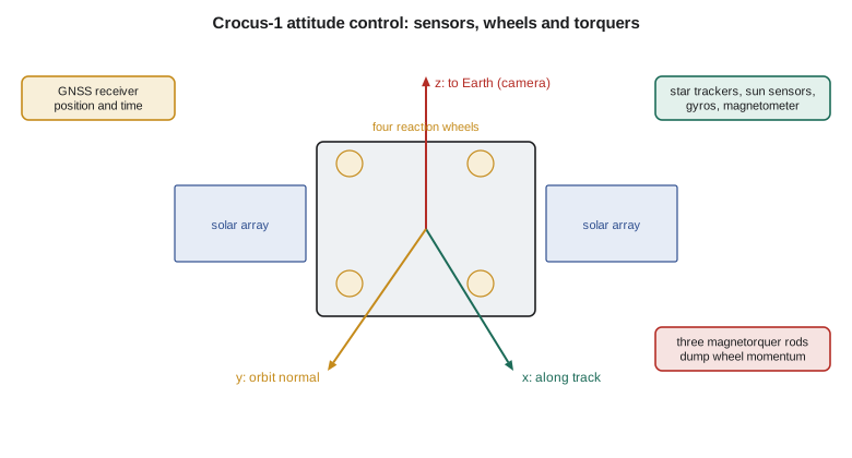
A reaction wheel is a flywheel driven by an electric motor. To rotate the spacecraft one way, the motor spins the wheel the other way; the total angular momentum stays constant, so the body turns. Wheels give smooth, precise torques and are the actuator of choice for fine pointing. Crocus-1 carries four wheels in a pyramid arrangement, so that any three can control all three axes if one fails. Larger spacecraft, especially agile imaging satellites and space stations, use control moment gyroscopes, which tilt a constantly spinning wheel to produce much larger torques.
Wheels absorb disturbance torques by changing speed. A steady disturbance makes a wheel spin faster and faster until it reaches its maximum speed, a condition called saturation. Before then the stored momentum must be removed, or dumped, with an external torque. In low Earth orbit the simplest way is a magnetorquer, an electromagnet that pushes against the Earth's magnetic field. The torque is \(\mathbf{T} = \mathbf{m}\times\mathbf{B}\), where \(\mathbf{m}\) is the magnetic dipole and \(\mathbf{B}\) the local field, about 30 µT at 550 km. Crocus-1's 10 A m² rods produce roughly 150 µN m on average, enough to dump an orbit's accumulated momentum in about a minute. Magnetorquers have no moving parts and use no propellant, but they cannot produce torque along the field direction, so the control law uses the changing direction of the field around the orbit to reach every axis.
Thrusters provide large torques and are used during orbit maneuvers, when misalignment of the main thrust would overwhelm the wheels, and for momentum dumping at altitudes where the magnetic field is weak, such as geostationary orbit. Crocus-1's propulsion module has four small thrusters arranged so that firing pairs can produce torques as well as translation.
Slewing
Dr. Benali's fire monitoring for the Kansas Forest Service sometimes needs off-nadir images, pointing the camera up to 30 degrees to the side to catch a fire that the ground track misses. The fastest way to rotate through an angle \(\theta\) with a fixed maximum torque is bang-bang control: full torque to accelerate for half the maneuver, full opposite torque to brake for the other half. The slew time is
With a wheel torque of 20 mN m and an inertia of 14 kg m² about the roll axis, a 30 degree slew takes 38 seconds, peaks at 1.57 degrees per second and needs 0.38 N m s of wheel momentum, within the 0.5 N m s limit. In practice the profile is smoothed at the start and end to avoid exciting the solar arrays, which adds a few seconds, and the spacecraft must settle before imaging starts. The slew time sets how many off-nadir targets the satellite can image on one pass: at 7.6 km/s, a 40 second slew and settle covers 300 km of ground track.
Sensors and attitude determination
No single sensor measures the full attitude well, so spacecraft combine several. Star trackers photograph the sky and match the stars to a catalog, giving the full attitude to a few arcseconds; they are the precision sensor for imaging missions. Sun sensors give the Sun's direction, coarsely but robustly, and are used in safe mode. Magnetometers measure the Earth's field vector, which, compared with a field model at the known position, gives a second reference direction. Gyroscopes measure angular rate and are integrated between star tracker updates. Earth horizon sensors find the local vertical from the infrared edge of the Earth. GNSS receivers supply position and time, needed to know where the Earth, Sun and target are.
The flight software fuses these measurements with an estimator, usually an extended Kalman filter, that propagates the attitude with the gyro rates and corrects it whenever a star tracker or other measurement arrives. Attitudes are represented internally by quaternions, four-parameter descriptions that avoid the singularities of three Euler angles and are cheap to propagate. Star trackers can be blinded by the Sun, Moon or Earth, so Crocus-1 carries two, mounted so that at least one always has a clear view.
Pointing requirements come in more than one kind. Accuracy is how close the boresight is to the commanded direction on average; knowledge is how well the actual direction is known after the fact, which matters for placing each pixel on the map; and stability, or jitter, is how much the boresight moves during one exposure. Crocus-1's push-broom camera builds an image line by line as the satellite moves, so jitter at frequencies of a few hertz to a few hundred hertz smears the image. Reaction wheels are the main source: an imbalance in a wheel spinning at thousands of revolutions per minute shakes the structure. Lavoie specifies balanced wheels, mounts them on small isolators, and keeps the wheel speeds away from the structural resonances that Marcus Webb's analysis identifies. The pointing budget allocates the 0.1 degree accuracy among sensor errors, control errors, structural misalignment between the camera and the star trackers, and thermal distortion as the spacecraft moves between sunlight and eclipse.
Modes and safe mode
The control system runs in modes. After separation, in detumble mode, magnetorquers alone reduce the tumble rates using a simple law that opposes the measured change in the magnetic field. In Sun-pointing mode, coarse sensors and wheels point the solar arrays at the Sun to secure power. In nadir mode, the normal operating mode, the camera points at the Earth with full star tracker accuracy. Safe mode is a simple, robust Sun-pointing mode that the spacecraft falls back to automatically if it detects a fault, using only the most reliable sensors and keeping the battery charged until the ground team diagnoses the problem. Lavoie's team tests every transition between modes on a hardware-in-the-loop bench before launch.
| Item | Value | Source |
|---|---|---|
| Pointing accuracy required | 0.1 degree | imaging |
| Total disturbance torque | about 5.3 µN m | code |
| Momentum per orbit | about 9.7 mN m s | code |
| Wheel capacity | 0.5 N m s each, four wheels | selected hardware |
| 30 degree slew | 38 s with 20 mN m | bang-bang |
| Magnetorquer dump | about 1 min per orbit of momentum | code |
Worked problem
Gravity-gradient torque
Find the gravity-gradient torque at a 3 degree offset for \(I_z = 9\) kg m², \(I_y = 16\) kg m² at 550 km.
Show solution
- \(n = 1.095\times10^{-3}\) rad/s, so \(n^2 = 1.199\times10^{-6}\) s\(^{-2}\).
- \(T = 1.5(1.199\times10^{-6})(7)\sin 6^\circ = 1.5(1.199\times10^{-6})(7)(0.1045)\).
Answer: \(1.32\times10^{-6}\) N m.
Worked problem
Slew time
How long does a 30 degree bang-bang slew take with \(T = 0.020\) N m and \(I = 14\) kg m²?
Show solution
- \(\theta = 0.5236\) rad.
- \(t = 2\sqrt{0.5236(14)/0.020} = 2\sqrt{366.5} = 2(19.14)\).
Answer: 38.3 s.
Worked problem
Magnetorquer torque
Estimate the average torque from a 10 A m² magnetorquer in a 30 µT field with an efficiency factor of 0.5.
Show solution
- \(T = 0.5(10)(30\times10^{-6})\).
Answer: 150 µN m.
Common mistakes
MistakeSpinning a flexible spacecraft about its minimum-inertia axis.
InsteadWith energy dissipation only maximum-axis spin is stable.
MistakeSizing wheels for torque but not momentum.
InsteadCheck both the slew torque and the stored momentum against saturation.
MistakeForgetting that magnetorquers cannot act along the field.
InsteadUse the field's rotation around the orbit to reach all axes.
MistakeUsing Euler angles in flight software.
InsteadQuaternions avoid singularities.
MistakeRelying on a single star tracker.
InsteadSun and Earth can blind it; carry two with different views.
Summary and key terms
- Attitude control combines determination with sensors and control with actuators.
- Euler's equations describe rigid-body rotation and explain why only spin about the major axis is stable with dissipation.
- Gravity-gradient, magnetic, solar and drag torques of a few micronewton-meters act on Crocus-1.
- Reaction wheels absorb them and provide precise pointing and slews, and magnetorquers dump the stored momentum.
- Star trackers, gyros, magnetometers and Sun sensors feed a Kalman filter.
- Modes from detumble to nadir, with a robust safe mode, structure the operations.
- Euler's equations
- The equations of rotational motion in body axes.
- Three-axis stabilization
- Active control of all three rotation axes.
- Gravity-gradient torque
- The torque from the variation of gravity across a spacecraft.
- Reaction wheel
- A motor-driven flywheel that exchanges momentum with the spacecraft.
- Saturation
- A wheel reaching its maximum speed and unable to absorb more momentum.
- Magnetorquer
- An electromagnet that produces torque against the Earth's field.
- Star tracker
- A camera that determines attitude from star patterns.
- Safe mode
- A robust fallback mode that keeps the spacecraft power-positive.
Practice problems
Work each problem on paper first, then reveal the answer to check.
Which spin axis is stable for a dissipative body?
Show answer
The axis of maximum inertia.
What is the total disturbance torque on Crocus-1?
Show answer
About 5.3 µN m.
Why four reaction wheels instead of three?
Show answer
Any three can control all axes if one fails.
How is wheel momentum removed in low Earth orbit?
Show answer
With magnetorquers acting against the Earth's field.
Which sensor gives arcsecond attitude knowledge?
Show answer
The star tracker.
What does detumble mode use?
Show answer
Magnetorquers with a law that opposes the change in measured field.
Lesson quiz · 5 questions
Score 60% or more to complete this lesson.
Create a free account to save your progress, take quizzes and earn a certificate.