
AERO-340 · Lesson 3 of 12 · 26 min
Brayton cycle analysis
Every gas turbine, from the Tern's 665 kW range extender to the largest airliner engine, runs on the Brayton cycle: compress air, add heat at nearly constant pressure, expand the hot gas through a turbine, and reject heat to the atmosphere through the exhaust. Thermodynamics II already derived the ideal cycle and looked at it as a power plant. This lesson takes the aircraft engine designer's view. Dr. Nakamura asks Arjun to explain to the Swift 900 program managers why the two engine proposals they received differ so much: one has a core pressure ratio of 16 and a turbine inlet temperature of 1450 K, the other 26 and 1650 K. To do it he needs the real cycle, with component losses, and its two key outputs: how much work each kilogram of air delivers and how efficiently the fuel is used.
The ideal cycle in brief
In the ideal Brayton cycle the compression and expansion are isentropic and the gas is perfect with constant specific heats. States 1 to 4 are compressor inlet, compressor exit, turbine inlet and turbine exit. With the pressure ratio \(\pi = p_2/p_1\) and \(\gamma\) the ratio of specific heats, the thermal efficiency is
It depends only on the pressure ratio. The net specific work, the shaft work per kilogram of air, also depends on the turbine inlet temperature \(T_3\):
For a fixed \(T_3\) the work rises with pressure ratio, reaches a maximum, and falls back to zero when the compressor exit temperature reaches \(T_3\) and there is no room left to add heat. The maximum occurs where \(T_2 = T_4\), at a pressure ratio of \((T_3/T_1)^{\gamma/(2(\gamma-1))}\).
Real components
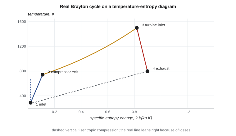
Real compressors and turbines generate entropy. Their performance is described by isentropic efficiencies, which compare the actual temperature change with the isentropic one between the same pressures:
The compressor needs more work than the ideal one, and the turbine gives less. Add a few percent of total pressure loss through the combustor and ducts, and use different gas properties for the hot side (about 1150 J/(kg K) and \(\gamma = 1.33\) for combustion products, against 1005 and 1.4 for air), and the cycle changes character. Because the turbine work and compressor work are two large numbers whose difference is the net output, small losses in each take a large bite out of the net work. A compressor efficiency of 0.86 and a turbine efficiency of 0.90 typically cut the net work by a quarter or more.
What the real cycle shows
The real cycle brings in a second important parameter: the cycle temperature ratio \(T_3/T_1\). In the ideal cycle, efficiency depends on pressure ratio alone. In the real cycle, a higher turbine inlet temperature makes the losses a smaller fraction of the work, so efficiency rises with temperature too. And the best pressure ratio for efficiency is much higher than the best pressure ratio for specific work. That gives designers a real choice.
# Brayton cycle with component efficiencies: thermal efficiency and specific work
# against pressure ratio, ideal and real, for a turbine inlet temperature of 1500 K.
cp, g = 1005.0, 1.4; cpg, gg = 1150.0, 1.33
T1 = 288.15
def cycle(pr, T3, eta_c=0.86, eta_t=0.90, loss=0.04, ideal=False):
    if ideal:
        T2 = T1 * pr ** ((g - 1) / g); T4 = T3 / pr ** ((g - 1) / g)
        w = cp * (T3 - T4) - cp * (T2 - T1); q = cp * (T3 - T2)
        return w / 1000, w / q
    T2 = T1 * (1 + (pr ** ((g - 1) / g) - 1) / eta_c)
    pr_t = pr * (1 - loss)                         # combustor and duct pressure losses
    T4 = T3 * (1 - eta_t * (1 - pr_t ** (-(gg - 1) / gg)))
    w = cpg * (T3 - T4) - cp * (T2 - T1); q = cpg * (T3 - T2)
    return w / 1000, w / q
print(" pr   ideal w kJ/kg  ideal eta   real w kJ/kg  real eta")
best = (0, 0)
for pr in (4, 8, 12, 16, 20, 25, 30, 40):
    wi, ei = cycle(pr, 1500, ideal=True); wr, er = cycle(pr, 1500)
    best = max(best, (wr, pr))
    print(f"{pr:3d}     {wi:6.1f}       {ei:5.3f}       {wr:6.1f}      {er:5.3f}")
print(f"\nreal-cycle specific work peaks near pressure ratio {best[1]} ({best[0]:.0f} kJ/kg)")
for T3 in (1300, 1500, 1700):
print(f"TIT {T3} K, pr 20: real w {cycle(20, T3)[0]:5.1f} kJ/kg, eta {cycle(20, T3)[1]:.3f}")pr ideal w kJ/kg ideal eta real w kJ/kg real eta 4 352.3 0.327 277.0 0.230 8 440.3 0.448 343.1 0.317 12 466.9 0.508 357.8 0.359 16 474.9 0.547 357.4 0.385 20 475.0 0.575 350.9 0.402 25 469.7 0.601 338.9 0.417 30 461.4 0.622 325.0 0.427 40 440.8 0.651 295.2 0.438 real-cycle specific work peaks near pressure ratio 12 (358 kJ/kg) TIT 1300 K, pr 20: real w 243.4 kJ/kg, eta 0.379 TIT 1500 K, pr 20: real w 350.9 kJ/kg, eta 0.402 TIT 1700 K, pr 20: real w 458.5 kJ/kg, eta 0.416
The program shows the trade clearly. In the ideal cycle at 1500 K, specific work peaks near a pressure ratio of 16 to 20 at 475 kJ/kg and efficiency keeps rising. With real components, the specific work peaks earlier, near a pressure ratio of 12, at only 358 kJ/kg, while efficiency still climbs, from 0.36 at 12 to 0.44 at 40. Raising the turbine inlet temperature from 1300 to 1700 K at a pressure ratio of 20 nearly doubles the specific work, from 243 to 459 kJ/kg, and lifts the efficiency from 0.38 to 0.42.
Arjun's explanation to the program managers follows directly. The higher-pressure, hotter engine will have better cycle efficiency, which means lower fuel burn, and more work per kilogram of air, which means a smaller, lighter core for the same thrust. The price is turbine materials and cooling for 1650 K (Lesson 10), more compressor stages or higher blade speeds for a pressure ratio of 26 (Lesson 8), and typically higher maintenance cost. Whether the fuel saving pays for those depends on how the Swift 900's customers fly. Business jets fly fewer hours per year than airliners, which makes the fuel saving worth less and the maintenance cost relatively more important.
| Cycle choice | Effect on efficiency | Effect on specific work | Cost |
|---|---|---|---|
| Higher pressure ratio | Rises | Rises then falls | More stages, higher compressor exit temperature |
| Higher turbine inlet temperature | Rises (real cycle) | Rises strongly | Advanced alloys, coatings and cooling |
| Better component efficiencies | Rises | Rises | Design effort, tighter clearances, cost |
| Lower pressure losses | Rises slightly | Rises slightly | Larger ducts, careful combustor design |
From the shaft cycle to aircraft engines
A shaft engine, like the Tern's turboshaft, takes all its useful output as turbine work and leaves the exhaust slow. A jet engine uses the turbine only to drive the compressor and lets the remaining energy accelerate the exhaust through a nozzle. The thermodynamic cycle is the same; what changes is where the useful energy is taken out. Lessons 4 to 6 treat the turbojet, turbofan and turboprop as different ways of dividing the cycle's energy between shaft and jet. In each, the designer's first decision is the core pressure ratio and turbine inlet temperature, which set the cycle, and the second is how to turn the cycle's energy into thrust most efficiently, which sets the propulsive efficiency.
Two practical additions modify the simple cycle. A recuperator, a heat exchanger that heats compressor exit air with turbine exhaust, raises efficiency at low pressure ratios and is used in some ground turbines and small experimental aircraft engines, but it is too heavy and bulky for most aircraft. Intercooling between compressor stages saves compressor work, but again the heat exchanger weight usually rules it out. For aircraft, pressure ratio and temperature are the main levers.
Worked problem
Ideal cycle efficiency and optimum pressure ratio
An ideal Brayton cycle has \(T_1 = 288\) K and \(T_3 = 1400\) K with \(\gamma = 1.4\). Find the pressure ratio for maximum specific work and the thermal efficiency at that pressure ratio.
Show solution
- \(\pi_{opt} = (1400/288)^{1.4/0.8} = 4.861^{1.75} = 15.9\).
- \(\eta_{th} = 1 - 15.9^{-0.2857} = 1 - 0.454 = 0.546\).
Answer: A pressure ratio of about 16 gives the most work per kilogram, at a thermal efficiency of 0.55.
Worked problem
Real compressor exit temperature
Air at 288 K is compressed through a pressure ratio of 20 with an isentropic efficiency of 0.86. Find the exit temperature and the compressor work per kilogram.
Show solution
- \(T_{2s} = 288 \times 20^{0.2857} = 288 \times 2.354 = 678\) K.
- \(T_2 = 288 + (678 - 288)/0.86 = 288 + 453 = 741\) K.
- \(w_c = 1005 \times 453 = 455\) kJ/kg.
Answer: Exit temperature 741 K, compressor work 455 kJ/kg, 72 kJ/kg more than the isentropic value.
Worked problem
Turbine work with losses
Combustion gas at 1500 K expands through a pressure ratio of 19.2 with \(\gamma = 1.33\), \(c_p = 1150\) J/(kg K) and an isentropic efficiency of 0.90. Find the turbine exit temperature and work.
Show solution
- \(T_{4s} = 1500 \times 19.2^{-0.248} = 1500 \times 0.480 = 720\) K.
- \(T_4 = 1500 - 0.90 \times (1500 - 720) = 798\) K.
- \(w_t = 1150 \times 702 = 807\) kJ/kg.
Answer: The turbine gives 807 kJ/kg; subtracting the 455 kJ/kg compressor work leaves about 350 kJ/kg net, as in the program.
Off-design operation
An engine spends little of its life at its design point. At part power the turbine inlet temperature falls, the compressor runs at lower speed and pressure ratio, and the cycle efficiency drops. A gas turbine at 30 percent power may use 40 to 60 percent more fuel per unit of output than at full power. That is one reason aircraft cruise engines are sized so that cruise falls near their best efficiency, and why the Tern's turboshaft was sized for cruise rather than take-off: the battery handles the peaks, and the turbine runs close to its design point for most of the flight.
Ambient conditions matter too. On a hot day the compressor inlet temperature rises, which lowers the cycle temperature ratio \(T_3/T_1\) and with it both specific work and efficiency at a given turbine inlet temperature. To protect the turbine, engines are flat rated: they deliver full take-off thrust up to a certain ambient temperature, often around ISA plus 15 to 30 K, by running cooler than their limit on cold days, and lose thrust above it. That is why take-off performance charts show a corner temperature, and why hot, high airports limit payload.
Worked problem
Effect of a hot day on the cycle
An engine has \(T_3 = 1500\) K. Compare the cycle temperature ratio on a standard day at 288 K and a hot day at 313 K.
Show solution
- Standard: \(1500/288 = 5.21\).
- Hot: \(1500/313 = 4.79\), about 8 percent lower.
Answer: The hot day cuts specific work noticeably at the same turbine temperature, so the engine either loses thrust or must run hotter, shortening blade life.
Engine makers compare cycles on a carpet plot, a chart of thermal efficiency against specific work with lines of constant pressure ratio and constant turbine inlet temperature. The best engines sit toward the upper right, and the plot shows at a glance what a given increase in temperature or pressure ratio buys. Arjun's slides to the Swift 900 program managers end with one: the two proposals sit on different corners of it, and the choice between them is a business decision as much as a technical one.
Common mistakes
MistakeUsing the ideal efficiency formula for a real engine.
InsteadReal efficiency also depends on turbine inlet temperature and component efficiencies.
MistakeAssuming the best pressure ratio for work is also best for efficiency.
InsteadEfficiency keeps rising with pressure ratio well past the work peak.
MistakeUsing air properties throughout.
InsteadHot combustion products have higher cp and lower gamma; using air properties overstates turbine work.
MistakeForgetting combustor pressure loss.
InsteadA few percent loss reduces the turbine pressure ratio and the net work.
Summary and key terms
- The Brayton cycle compresses air, adds heat at nearly constant pressure and expands through a turbine.
- The ideal efficiency depends only on pressure ratio, while specific work also depends on turbine inlet temperature and peaks at an intermediate pressure ratio.
- Real components cut net work sharply because it is the difference of two large numbers, and make efficiency depend on temperature as well.
- Higher pressure ratio and turbine inlet temperature give better efficiency and a smaller core but cost more in materials, cooling and maintenance.
- Brayton cycle
- The gas turbine cycle of compression, constant-pressure heat addition, expansion and heat rejection.
- Isentropic efficiency
- Ideal temperature change divided by actual, for compressors; the inverse ratio for turbines.
- Specific work
- Net shaft work per kilogram of air through the cycle.
- Turbine inlet temperature
- The gas temperature entering the first turbine stage, the hottest point of the cycle.
- Cycle temperature ratio
- Turbine inlet temperature divided by compressor inlet temperature.
- Recuperator
- A heat exchanger that preheats compressor exit air with exhaust heat.
Practice problems
Work each problem on paper first, then reveal the answer to check.
What is the ideal thermal efficiency at a pressure ratio of 30?
Show answer
About 0.62.
Why does real net work fall so much more than turbine or compressor work alone?
Show answer
It is the small difference between two large numbers, so losses in each subtract directly.
In the program, set the compressor efficiency to 0.90. What happens to the pressure ratio for maximum work?
Show answer
It moves higher, to about 15, and the peak work rises to about 376 kJ/kg.
Which raises specific work more strongly, higher pressure ratio or higher turbine inlet temperature?
Show answer
Higher turbine inlet temperature.
Why are recuperators rare on aircraft engines?
Show answer
Their weight and bulk outweigh the efficiency gain at aircraft pressure ratios.
A cycle has T3 = 1600 K and T1 = 250 K at altitude. What is the ideal optimum pressure ratio for work?
Show answer
About 25.8.
Lesson quiz · 5 questions
Score 60% or more to complete this lesson.
Create a free account to save your progress, take quizzes and earn a certificate.