
AERO-340 · Lesson 2 of 12 · 24 min
Piston engines and propellers
The Tern's propellers are turned by electric motors, but most propellers in the world are still turned by piston engines, and the basic ideas of propeller performance were worked out on them. Prairiewind Aerospace keeps a small fleet of Plover two-seat trainers at Wichita's airport for its pilots' currency flying, each with a 134 kW (180 hp) four-cylinder engine and a two-blade propeller. When the flying club asked whether a turbocharged engine would let the Plover keep its climb rate on summer days at altitude, Dr. Nakamura gave the question to Arjun as a warm-up. It covers both halves of this lesson: how a piston engine's power changes with altitude, and how a propeller turns shaft power into thrust.
The four-stroke engine in brief
An aircraft piston engine is a spark-ignition engine running on the Otto cycle: intake, compression, power and exhaust strokes, with one power stroke for every two crankshaft revolutions in each cylinder. Most light aircraft engines are horizontally opposed, air cooled, with four or six cylinders, two spark plugs per cylinder from two independent magnetos, and a fixed or controllable-pitch propeller bolted directly to the crankshaft. Their power is roughly proportional to the mass of air they can draw into the cylinders each minute, because the fuel burned is limited by the oxygen available. That one fact explains how they behave with altitude.
Brake power, the power at the crankshaft, can be written as
where \(V_d\) is the displacement, \(N\) the revolutions per second, \(\eta_v\) the volumetric efficiency, \(\rho\) the density of the intake air and \(A/F\) the air-fuel ratio. Everything on the right except the density is set by the engine and how it is operated. As the aircraft climbs, density falls and so does the power.
Power lapse with altitude
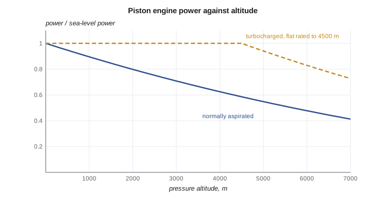
A normally aspirated engine loses power faster than density alone suggests, because friction and accessory losses stay roughly constant while the indicated power falls. A widely used empirical form is the Gagg and Ferrar relation,
where \(\sigma = \rho/\rho_0\) is the density ratio. At 3000 m (about 10,000 ft), where \(\sigma\) is 0.74, the engine gives about 71 percent of its sea-level power. Pilots meet the same effect on hot days at high airports: density altitude, not field elevation, decides the power available.
A turbocharger fights the lapse. Exhaust gas drives a small turbine on a shaft with a centrifugal compressor that pressurizes the intake air. A wastegate bypasses exhaust around the turbine at low altitude, so the manifold pressure is held at its sea-level value; as the aircraft climbs, the wastegate closes to send more exhaust through the turbine. At the critical altitude the wastegate is fully closed and above it the power falls again. The cost is weight, heat, complexity and careful engine management: the pilot must watch manifold pressure and turbine inlet temperature, and cool the engine down gently after flight.
Propellers: momentum theory
A propeller is a rotating wing. Its blades produce lift whose forward component is thrust, and drag whose torque the engine must overcome. The simplest model ignores the blades altogether and treats the propeller as an actuator disc that adds a pressure jump to the air passing through it. Applying mass, momentum and energy conservation to the stream tube through the disc gives three results. The velocity at the disc is the average of the far upstream and far downstream speeds, so half the final velocity increase happens before the disc. The induced velocity at the disc, \(v_i\), satisfies
and the ideal efficiency is the Froude efficiency of Lesson 1 written for the disc, \(\eta_i = V_0/(V_0 + v_i)\). For a given thrust, a bigger disc means a smaller induced velocity and a higher ideal efficiency. That is the propeller's version of the large, slow stream. It also shows why efficiency is poor at low speed and high thrust, such as the take-off roll: there the induced velocity is large compared with the flight speed.
Propeller coefficients and blade angle
Real propellers are described by non-dimensional coefficients. With rotational speed \(n\) in revolutions per second and diameter \(D\):
The advance ratio \(J\) is the distance the aircraft moves in one revolution, divided by the diameter. It sets the angle at which the air meets each blade section. For a fixed blade angle there is one advance ratio at which efficiency peaks; at lower \(J\) the blades are at a high angle of attack, at higher \(J\) the angle of attack falls toward zero and thrust vanishes. A fixed-pitch propeller is a compromise between climb and cruise. A constant-speed propeller changes blade angle with a governor to hold the engine speed the pilot selects, so it rides the top of the family of efficiency curves.
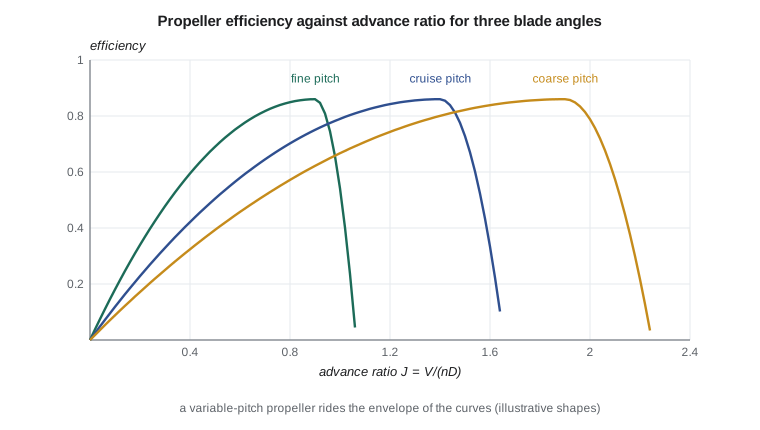
Blade element theory fills in what momentum theory leaves out. Each blade is divided into strips; at each strip the relative velocity is the vector sum of the flight speed plus induced velocity and the rotational speed \(2\pi n r\). Airfoil lift and drag data give the force on the strip, and integrating along the blade gives thrust and torque. Profile drag, swirl in the slipstream, tip losses and compressibility at the tips all reduce efficiency below the momentum value. Good propellers reach about 85 to 88 percent at cruise.
Compressibility sets a hard limit. The blade tips move along a helix whose speed combines rotation and flight speed; when the helical tip Mach number exceeds about 0.85 to 0.9, shock waves form, efficiency drops and noise rises sharply. Large slow-turning propellers, reduction gearboxes on turboprops and swept, thin blade tips are all ways of keeping the tips subsonic.
# Piston engine power lapse with altitude, and propeller performance by momentum theory
# and the non-dimensional coefficients, for the Plover trainer and the Tern.
import math

def isa(h):                                     # troposphere, h in m
    T = 288.15 - 0.0065 * h
    p = 101325 * (T / 288.15) ** 5.2559
    return T, p, p / (287.05 * T)

P0 = 134.0                                      # kW, Plover's normally aspirated engine at sea level
print("altitude m   sigma   Gagg-Ferrar P kW   turbocharged P kW (flat to 4500 m)")
for h in (0, 1500, 3000, 4500, 6000):
    T, p, rho = isa(h); sigma = rho / 1.225
    P_na = P0 * (1.132 * sigma - 0.132)
    P_tc = P0 if h <= 4500 else P0 * (1.132 * (rho / isa(4500)[2]) - 0.132)
    print(f"{h:8d}    {sigma:5.3f}      {P_na:7.1f}            {P_tc:7.1f}")

def momentum(T_N, V, D, rho):
    A = math.pi * D**2 / 4
    vi = -V / 2 + math.sqrt((V / 2)**2 + T_N / (2 * rho * A))   # induced velocity at the disc
    eta_i = V / (V + vi)                                           # ideal (Froude) efficiency
    return vi, eta_i, T_N * (V + vi) / 1000                       # ideal power, kW

print("\nTern propeller, D = 2.6 m, 1700 rpm, cruise at 3000 m")
T, p, rho = isa(3000)
for V, F in ((45.0, 6000.0), (70.0, 4200.0), (105.0, 2310.0)):
    vi, eta_i, Pi = momentum(F, V, 2.6, rho)
    n = 1700 / 60; J = V / (n * 2.6)
    CT = F / (rho * n**2 * 2.6**4)
    eta_real = 0.85 * eta_i if V > 60 else 0.80 * eta_i          # profile and swirl losses, illustrative
    P_shaft = F * V / eta_real / 1000
    CP = P_shaft * 1000 / (rho * n**3 * 2.6**5)
    print(f"V {V:5.1f} m/s  J {J:4.2f}  CT {CT:5.3f}  CP {CP:5.3f}  ideal eta {eta_i:4.2f}  "
          f"realistic eta {eta_real:4.2f}  shaft power {P_shaft:5.0f} kW")
tip = math.hypot(math.pi * 2.6 * 1700 / 60, 105.0) / math.sqrt(1.4 * 287.05 * T)
print(f"\nhelical tip Mach number at cruise {tip:.2f}")altitude m sigma Gagg-Ferrar P kW turbocharged P kW (flat to 4500 m)
0 1.000 134.0 134.0
1500 0.864 113.3 134.0
3000 0.742 94.9 134.0
4500 0.634 78.5 134.0
6000 0.539 64.0 111.1
Tern propeller, D = 2.6 m, 1700 rpm, cruise at 3000 m
V 45.0 m/s J 0.61 CT 0.180 CP 0.171 ideal eta 0.80 realistic eta 0.64 shaft power 421 kW
V 70.0 m/s J 0.95 CT 0.126 CP 0.152 ideal eta 0.92 realistic eta 0.79 shaft power 374 kW
V 105.0 m/s J 1.43 CT 0.069 CP 0.119 ideal eta 0.98 realistic eta 0.83 shaft power 291 kW
helical tip Mach number at cruise 0.77The program answers the flying club's question first. The Plover's normally aspirated engine gives 95 kW at 3000 m and 79 kW at 4500 m; a turbocharger flat rated to 4500 m would keep the full 134 kW up there, a large gain for climb on hot days and for flying over the Rockies west of Colorado. Dr. Nakamura's comment was that the flying club also needs to price the overhaul cost and the training for turbocharger management before deciding.
For the Tern propeller, the momentum results show the classic pattern. At 45 m/s in the initial climb, the ideal efficiency is 0.80 and the realistic value, with profile and swirl losses, about 0.64, so 6.0 kN of thrust needs 421 kW of shaft power, close to the motor's 450 kW rating. At 105 m/s cruise the ideal efficiency is 0.98 and the realistic value 0.83, and 2.31 kN needs 291 kW. The helical tip Mach number at cruise is 0.77, safely below the range where compressibility losses begin. The realistic efficiencies use fixed loss factors and are illustrative; the company's propeller supplier provides full performance maps.
| Quantity | Symbol | Meaning |
|---|---|---|
| Advance ratio | J = V/(nD) | Distance flown per revolution over diameter |
| Thrust coefficient | CT = T/(rho n² D⁴) | Non-dimensional thrust |
| Power coefficient | CP = P/(rho n³ D⁵) | Non-dimensional shaft power |
| Efficiency | eta = J CT/CP | Thrust power over shaft power |
| Helical tip Mach | sqrt((pi n D)² + V²)/a | Must stay below about 0.85 |
Worked problem
Power lapse
A normally aspirated engine gives 150 kW at sea level. What does the Gagg and Ferrar relation predict at a density altitude where \(\sigma = 0.80\)?
Show solution
- \(P/P_0 = 1.132 \times 0.80 - 0.132 = 0.774\).
- \(P = 0.774 \times 150 = 116\) kW.
Answer: About 116 kW (156 hp). The density alone would suggest 120 kW; friction losses make it a little worse.
Worked problem
Induced velocity and ideal efficiency
A propeller of 2.0 m diameter gives 3000 N at 50 m/s in air of density 1.1 kg/m³. Find the induced velocity and ideal efficiency.
Show solution
- \(A = \pi \times 2.0^2/4 = 3.14\) m².
- \(3000 = 2 \times 1.1 \times 3.14\,(50 + v_i)\,v_i\), so \(v_i^2 + 50 v_i - 434 = 0\) and \(v_i = 7.7\) m/s.
- \(\eta_i = 50/57.7 = 0.87\).
Answer: Induced velocity 7.7 m/s, ideal efficiency 0.87. A real propeller would be around 0.75.
Worked problem
Advance ratio and tip Mach number
A 1.9 m propeller turns at 2400 rpm at 60 m/s where the speed of sound is 335 m/s. Find J and the helical tip Mach number.
Show solution
- \(n = 40\) rev/s, so \(J = 60/(40 \times 1.9) = 0.79\).
- Tip rotational speed \(= \pi \times 1.9 \times 40 = 239\) m/s; helical speed \(= \sqrt{239^2 + 60^2} = 246\) m/s.
- \(M_{tip} = 246/335 = 0.73\).
Answer: J is 0.79 and the tip Mach number 0.73, acceptable for a trainer.
Engine operation and fuel
Piston engines in light aircraft are leaned in cruise: the pilot reduces the fuel flow with a mixture control as altitude increases, because the thinner air needs less fuel for the best mixture. Most still burn leaded aviation gasoline, and the transition to unleaded fuels approved for existing engines is a major issue for the general aviation industry in both Canada and the United States. Diesel and jet-fuel piston engines, and electric trainers, are alternatives now in service in small numbers.
Common mistakes
MistakeAssuming piston power falls exactly with density.
InsteadFriction losses make the lapse somewhat steeper; use an empirical relation.
MistakeThinking a turbocharger adds power at sea level.
InsteadMost aircraft turbochargers hold sea-level power to a critical altitude; they do not raise the rating.
MistakeUsing momentum theory efficiency as the real propeller efficiency.
InsteadProfile drag, swirl and tip losses take another 10 to 15 percent.
MistakeIgnoring tip Mach number when increasing rpm or diameter.
InsteadSupersonic tips lose efficiency and make a lot of noise.
Summary and key terms
- Piston engine power is limited by the mass of air drawn in, so it falls with density altitude, a little faster than density because friction stays constant.
- Turbochargers hold sea-level manifold pressure up to a critical altitude.
- Propellers are rotating wings; momentum theory gives the induced velocity and an ideal efficiency that rises with disc area and flight speed.
- Advance ratio, thrust and power coefficients describe real propellers, constant-speed propellers ride the peak of the efficiency curves, and helical tip Mach number must stay subsonic.
- Density altitude
- The altitude in the standard atmosphere with the same air density as the actual conditions.
- Volumetric efficiency
- Mass of air actually drawn into a cylinder divided by the mass that would fill its displacement at intake conditions.
- Turbocharger
- An exhaust-driven turbine and compressor that pressurizes the intake air.
- Critical altitude
- The highest altitude at which a turbocharged engine can hold its rated manifold pressure.
- Actuator disc
- A model of a propeller as a thin disc that adds a pressure jump to the flow.
- Advance ratio
- Flight speed divided by rotational speed times diameter.
- Constant-speed propeller
- A propeller whose blade angle is changed automatically to hold a selected rpm.
Practice problems
Work each problem on paper first, then reveal the answer to check.
What fraction of sea-level power does a normally aspirated engine give where sigma is 0.60?
Show answer
About 0.55.
Why do turbocharged engines need a cool-down period after landing?
Show answer
The turbocharger runs very hot and its bearings need oil flow while it cools.
In the program, raise the Tern propeller diameter to 2.9 m. What happens to the cruise ideal efficiency and tip Mach number?
Show answer
Ideal efficiency rises slightly; tip Mach number rises to about 0.85, right at the limit.
A propeller has CT 0.08, CP 0.10 and J 1.2. What is its efficiency?
Show answer
0.96 by the formula; real values that high are rare, so check the data.
Why is propeller efficiency low during the take-off roll?
Show answer
Flight speed is low compared with the induced velocity, so the ideal efficiency is low.
What does a constant-speed propeller's governor change?
Show answer
The blade angle, to hold the selected rpm.
Lesson quiz · 5 questions
Score 60% or more to complete this lesson.
Create a free account to save your progress, take quizzes and earn a certificate.