
SMW-210 · Lesson 5 of 12 · 18 min
Triangulation principles and true-length diagrams
Triangulation is the most general method of pattern development in the trade. It develops a surface by dividing it into triangles small enough that each one is nearly flat, finding the true length of every side of every triangle, and then laying the triangles out on the sheet one after another, each sharing a side with the last. Any fitting that can be made from flat sheet can be developed this way, including the cones and frustums of the last three lessons. It is the only practical method for fittings whose element lines neither stay parallel nor meet at one apex: transitions from square to round, from one rectangle to another of a different shape, offset reducers, boots and twisted fittings. This lesson sets out the principles, the true-length diagram that makes the method quick, and the habits that keep a triangulated pattern accurate.
Why triangles
A triangle has a property no other shape has: if the lengths of its three sides are known, its shape is fixed. Three lengths give one triangle and only one, apart from its mirror image. That is what makes triangulation work. If a surface is divided into triangles, and the true length of each side is known, each triangle can be drawn flat on the sheet exactly as it is on the fitting. Lay the triangles out edge to edge in the same order they sit on the fitting, and the pattern is complete.
A surface made of flat faces, such as a hopper or a rectangle-to-rectangle transition, can be divided into triangles exactly, by drawing one diagonal across each four-sided face. A curved surface, such as the conical corners of a square-to-round, cannot be divided exactly, but it can be divided into many narrow triangles that together come very close to it. The more triangles, the closer the pattern. This is the same idea as dividing a pipe into 12 or 16 spaces in SMW-120: the divisions are an approximation that becomes as accurate as needed.
Plan, rise and true length
Triangulation depends entirely on true lengths, and Lesson 1 showed how to find them: the true length of a line is the hypotenuse of a right triangle whose sides are its plan length and its rise. On most transitions, the two ends of the fitting are flat and parallel, one at the bottom and one at the top, and every line running from one end to the other has the same rise, the height of the fitting. The plan lengths are measured from the plan view, and the rise is the same for all of them. That is why the true-length diagram is so efficient.
Lines that lie within one end of the fitting, such as the edges of a square end or the chords of a round end, have no rise. They are already true length in the plan, and the pattern uses them as they are. The BCcampus pattern development textbook gives the rule for transitions in a neat form: lines from a number to a letter, from one end to the other, need a true length; lines from a number to a number, or a letter to a letter, are true in the plan.
The true-length diagram
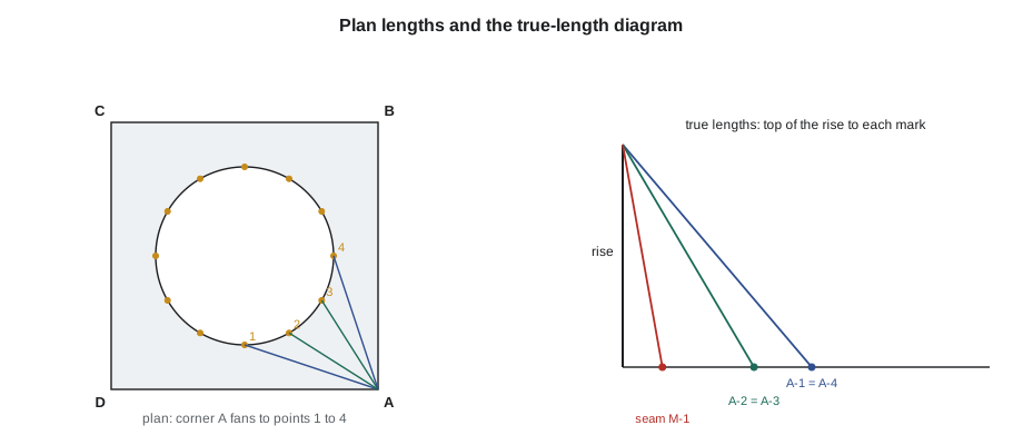
A true-length diagram, often called a TLD, is one right triangle drawn many times over on a common vertical. To build one:
- Draw a vertical line equal to the rise of the fitting, the vertical distance between its two ends. If the ends are not parallel, use a separate vertical for each rise.
- Draw a horizontal base line from the foot of the vertical, long enough to hold the longest plan length.
- Measure each sloping line's plan length from the plan view, with dividers or a rule, and mark it along the base line from the foot of the vertical. Label each mark with the line's name, such as A-1 or B-3.
- The distance from the top of the vertical to each mark is the true length of that line. Measure it, or set dividers to it, when drawing the pattern.
A good true-length diagram is labelled completely, even when several lines share a length. On a symmetrical fitting, line A-1 might be the same as D-7, but labelling both on the diagram, as the BCcampus textbook advises, stops the pattern maker from picking up the wrong length later. Kai's diagrams were drawn on the same sheet as the plan, to one side, so that plan lengths could be transferred directly with dividers.
Naming the points
Triangulation produces many points and many lines, and keeping them straight is half the battle. The convention used in most textbooks and shops is simple. The points on one end are numbered, 1, 2, 3 and so on, usually on the round end if there is one. The points on the other end are lettered, A, B, C and so on, usually on the square or rectangular end. Each line is named by its two ends, such as A-1. Plan lines are drawn solid, and the diagonals that split four-sided faces into triangles are often drawn dashed, so that the layout shows at a glance which lines are elements and which are diagonals.
The pattern's points carry the same names as the plan's points. When Kai found point 3 on the pattern, he labelled it 3 on the sheet right away, before moving on. A pattern with unlabelled points is a pattern in which, sooner or later, a length gets swung from the wrong point.
A simple example: an offset hopper
Aggie started Kai on a simple flat-sided fitting, the kind of offset hopper used under a filter bank or over a fan inlet, where every face is a four-sided flat or slightly warped panel. The large end was a rectangle 600 by 400 mm at floor level. The small end was a 300 mm square, 500 mm higher, set off to one side so that the back of the hopper was straight up. Each side face was split into two triangles by one diagonal, and every line ran from the bottom to the top, so every line had a rise of 500 mm.
The script below builds the table that a true-length diagram would give, from the plan coordinates and heights of the corners. It prints the plan length, the rise and the true length of every line. On paper, the same table would come from measuring the plan and the diagram; on a calculator, it comes from the right triangle.
# Build a true-length table from plan coordinates and heights (triangulation)
import math
pts = {'A': (0, 0, 0), 'B': (600, 0, 0), 'C': (600, 400, 0), 'D': (0, 400, 0),
       '1': (150, 100, 500), '2': (450, 100, 500), '3': (450, 400, 500), '4': (150, 400, 500)}   # mm        # name: (x, y, z) in plan, z = height above the base
lines = [('A', '1'), ('B', '2'), ('C', '3'), ('D', '4'), ('A', '2'), ('B', '3'), ('D', '3')]
print(f"{'line':<6}{'plan':>9}{'rise':>8}{'true':>9}")
for a, b in lines:
    (x1, y1, z1), (x2, y2, z2) = pts[a], pts[b]
    plan = math.hypot(x2 - x1, y2 - y1)
    rise = abs(z2 - z1)
print(f"{a + '-' + b:<6}{plan:>9.1f}{rise:>8.1f}{math.hypot(plan, rise):>9.1f}")line plan rise true A-1 180.3 500.0 531.5 B-2 180.3 500.0 531.5 C-3 150.0 500.0 522.0 D-4 150.0 500.0 522.0 A-2 461.0 500.0 680.1 B-3 427.2 500.0 657.6 D-3 450.0 500.0 672.7
With the table, the front face develops in four moves. Draw the bottom edge A-B at its plan length, which is true because it is horizontal. From A swing the true length of A-2, and from B swing the true length of B-2; where they cross is point 2. From A swing A-1, and from point 2 swing the top edge 1-2, true in the plan; where they cross is point 1. The front face is now laid out as two triangles, A-B-2 and A-2-1. The side faces follow, each sharing an edge with the face before it, until the pattern returns to its starting edge at the seam.
Developing in order
The single most important habit in triangulation is to develop the triangles in order, each one sharing a side with the last, so that the pattern grows as one connected piece. Every new point is found from two points already on the pattern, by two distances: one a true length from the diagram, the other a line that is true in the plan or another true length. The BCcampus textbook puts it as a rule worth memorizing: each new point is found from two known points, and the last point found becomes a known point for the next.
If a triangle is developed out of order, or a point is found from two points that are not adjacent on the fitting, the pattern still looks plausible but will not close. Errors also accumulate: a small mistake in one triangle carries into every triangle that follows it. That is why most layout people start at the middle of a symmetrical fitting and work outward toward the seams in both directions, which keeps the accumulated error to half the pattern.
Which side of the line
When two arcs are swung from two known points, they cross in two places, one on each side of the line joining the points. Only one of them is correct. On a simple fitting the right one is obvious, but on a twisted or offset fitting it is easy to pick the wrong one, which turns a triangle inside out and makes the pattern fold back on itself. The rule is that each new triangle lies on the far side of the shared line from the triangle before it, just as the next panel of the fitting lies beyond the edge it shares with the last one. Kai's habit was to rough-sketch each triangle before swinging its arcs, so he knew which crossing to take.
Straight lines and curves on the pattern
On the finished pattern, the edges that come from a flat end of the fitting are joined differently depending on the shape of that end. Points along a straight edge, such as the edge of a square end, are joined with straight lines. Points along a round end are joined with a smooth curve through all of them, drawn with a flexible batten or curve, because the round end of the fitting is a smooth circle, not a polygon. Kai's first square-to-round pattern had the round edge drawn as straight segments between the points, and the fitting came out with a faceted end that would not fit a round collar.
The element lines inside the pattern, A-1, A-2 and so on, become the bend lines where the sheet is formed. On a square-to-round, the lines from each corner to the round end fan out to form a conical corner, which is rolled or hand-formed in a smooth curve. The lines between the corner fans, the edges of the flat triangles on each side, are where the sheet stays flat. Marking which lines are bends and which are not, on the pattern, saves confusion at the brake.
Accuracy
Triangulation has two sources of error: the approximation of curved surfaces by triangles, and the accumulation of small drawing errors. The first is controlled by the number of divisions, as for pipes and cones. Twelve spaces on a round end are the usual minimum, and large or steep fittings use 16 or 24. The second is controlled by method: accurate plan lengths, sharp dividers, labelled points, triangles developed in order, and checks at the end.
Every triangulated pattern has at least one built-in check. On a fitting with a flat end, the edges along that end on the pattern must add up to the true perimeter of that end. On a square-to-round, the straight edges must add up to the square's perimeter and the curve through the round points must equal the round's mean circumference. The BCcampus textbook adds a geometric check for the on-centre square-to-round: the last triangle of a half pattern should make a right angle at the corner where it meets the seam. If the check fails, something upstream is wrong, and the fix is to go back, not to stretch the pattern to fit.
Common mistakes
MistakeUsing plan lengths for lines that run from one end to the other.
InsteadFind every end-to-end line's true length from the diagram; only lines within one end are true in the plan.
MistakeLabelling only the unique lengths on the true-length diagram.
InsteadLabel every line, even when several share a length.
MistakeDeveloping triangles out of order or from non-adjacent points.
InsteadFind each new point from two known adjacent points, and work in order from the middle out.
MistakeTaking the wrong crossing of two arcs.
InsteadEach new triangle lies beyond the shared line from the last; sketch it first.
MistakeJoining round-end points with straight segments.
InsteadDraw a smooth curve through round-end points with a batten; join square-end points with straight lines.
Summary and key terms
- Triangulation divides a surface into triangles, finds the true length of every side, and lays the triangles out in order.
- A triangle is fixed by its three sides, so known true lengths give an exact flat copy of each triangle.
- End-to-end lines need true lengths; lines within one end are true in the plan.
- A true-length diagram lays every plan length along a base from the foot of the rise, giving all the true lengths in one construction.
- Number one end, letter the other, label every point and line, and develop each new point from two known adjacent points.
- Check the pattern against the true perimeters of its ends before cutting.
- Triangulation
- Developing a surface by dividing it into triangles and laying them out flat in order.
- True-length diagram
- A construction that gives many true lengths from one rise and several plan lengths.
- Rise
- The vertical distance between the two ends of a line or fitting.
- Plan length
- The length of a line as it appears in the plan view.
- Diagonal
- A line drawn across a four-sided face to split it into two triangles.
- Warped surface
- A surface that is not flat and not a cone or cylinder, approximated by small triangles.
Practice problems
Work each problem on paper first, then reveal the answer to check.
A line has a plan length of 400 mm and the fitting's rise is 300 mm. What is its true length?
Show answer
500 mm.
Which lines on a square-to-round need no true-length construction?
Show answer
The edges of the square end and the chords of the round end, which lie flat in the plan.
Why work from the middle of a symmetrical pattern toward the seams?
Show answer
It keeps accumulated error to half the pattern.
What does it mean if the pattern's square edges do not add up to the square's perimeter?
Show answer
An error has been made upstream; go back and find it.
Lesson quiz · 5 questions
Score 60% or more to complete this lesson.
Create a free account to save your progress, take quizzes and earn a certificate.