
SMW-130 · Lesson 4 of 12 · 19 min
Transverse duct joints: slips, drives and flanges
A rectangular duct system is built from sections, and every section meets the next at a transverse joint. On a job like Ashgrove there were more than six hundred of them. Most were made overhead, on a lift or a ladder, by an installer holding the duct up with one hand. The transverse joint is therefore designed for two masters at once: the duct standard, which wants it strong, stiff and tight, and the installer, who wants it fast and possible to make in a cramped ceiling. This lesson covers the main families of rectangular transverse joint, what each one does, how each one is made and installed, and how they are rated.
What a transverse joint has to do
A transverse joint must join two sections so that air does not leak, keep the sections aligned so the duct runs straight, and stand up to the forces on the duct: its own weight between hangers, the internal pressure pushing or pulling on the walls, and vibration from the fan. In rectangular duct it often does a fourth job as well. A standing joint or flange stands out from the duct wall and stiffens it, the way a rib stiffens a panel, and the duct construction standards let some joints count as reinforcement. That can save adding separate angles or channels to the duct, which is why the choice of transverse joint is tied up with the choice of reinforcement, a subject SMW-220 covers in full.
The S slip and the drive slip
The simplest rectangular transverse joint is the slip and drive. Each end of a duct section has its edges folded back on themselves, or hemmed, by a small amount. On two opposite sides, usually the top and bottom, the sections are joined with S slips: long strips of sheet folded into an S shape, which slide over the hemmed edges of both sections. On the other two sides, the sections are joined with drive slips, or drive cleats: strips folded into a C shape that are driven along the hemmed edges from one end, locking the two sections together. The drives are made a little longer than the side of the duct, and the extra length is bent over the corners to lock them.
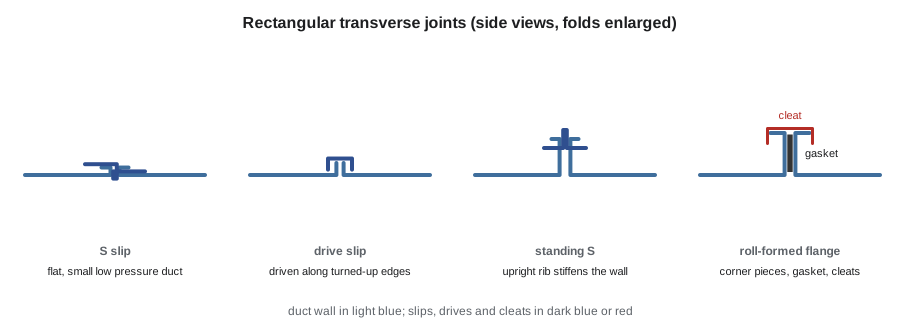
The S and drive joint is quick, cheap and works well on small, low pressure ducts. It is flat, so it adds little stiffness, and its long folded paths leak unless sealed. The duct construction standards limit flat S and drive joints to smaller duct sizes and lower pressure classes, and on larger ducts the plain S is replaced by a standing S.
Installing a drive is a two-handed job and an easy one to do badly. The drive is started at one corner with the sections held tightly together and aligned, then driven along the hems with a hammer, keeping the blows square to the end of the drive so it does not buckle. The drive must go its full length. A drive that stops short leaves a corner open, which is exactly what Kai's first leaks at Ashgrove came from. The tabs at the ends are then bent over the corners with a hand seamer or a hammer, locking the drive in place and closing the corner.
Standing joints
A standing S slip is an S slip whose middle is formed into an upright rib, so the joint stands out from the duct wall like a fin. The rib stiffens the wall, and taller standing seams stiffen it more. Standing S slips come in several heights and are used on the long sides of larger ducts, with drives on the short sides. Some standing S joints are reinforced further by slipping a flat bar or an angle into the rib, or by riveting a bar alongside it.
A standing drive slip is a drive formed with a raised rib, used in the same way. Together, standing S and standing drive joints allow slip-type joints on larger ducts and higher pressure classes than flat slips, within the limits the standard sets for each gauge, width and joint height.
Standing joints have one practical cost. They need clearance. A standing seam 25 mm (1 in) or more tall sticks out from the duct, which matters where ducts run close to each other, to the structure or to sprinkler pipes. Lin checks clearances on the coordination model before choosing tall standing joints for a congested ceiling.
Companion angle flanges
Before roll-formed flanges, the standard way to join large rectangular duct was the companion angle flange. A steel angle frame is attached around the end of each section, riveted or spot welded to the duct wall, with the duct turned out over the angle or sealed to it. The two frames are bolted together with a gasket between them. Companion angles are very strong, very stiff and suitable for high pressures and heavy industrial duct. They are also heavy, slow to make and expensive, and on most commercial work they have been replaced by roll-formed flanges. They are still used on heavy-gauge, high pressure and industrial systems, on connections to equipment and on duct that must be taken apart for cleaning.
Roll-formed flanges
The modern standard joint for medium and large rectangular duct is the roll-formed flange, often called by the trade names of the two original systems as a TDC or TDF joint. In a TDF-type joint, the flange is formed directly from the end of the duct wall on a roll former, so the duct and flange are one piece. In a TDC-type joint, a separate roll-formed flange profile is slipped over the end of the duct and fastened to it. Either way, each section ends in a flange all around. At the corners, steel corner pieces are dropped into the ends of the flange profiles. The two sections are brought together with a gasket between the flanges, bolted through the corner pieces, and then clamped along the sides with snap-on cleats or clips spaced along the flange.
Roll-formed flanges are fast in the shop, because the flange is formed automatically along with the section, and reasonably fast in the field. They are stiff, so they count as reinforcement at the joint, and with a good gasket and sealant at the corners they are tight. They allow larger duct and higher pressure classes than slip joints within the standard's limits. Their weak points are the corners, where the corner pieces meet the flange profiles, and the gasket, which must be continuous and lapped correctly at the corners.
On the Ashgrove gym mains, which were large and at the 750 Pa (3 in w.g.) pressure class, Lin specified roll-formed flanges throughout. The smaller classroom branches used standing S and drive joints. Kai spent a week on the gym mains with Sean's crew and learned the installation sequence for flanges.
- Check that each flange is straight and undamaged, and that the corner pieces are seated fully in the profile.
- Apply the gasket continuously around one flange, starting and finishing along a side rather than at a corner, with the ends butted tightly or lapped as the manufacturer directs.
- Bring the sections together and align them, then insert the corner bolts and tighten them evenly, working around the joint.
- Fit the cleats or clips along the sides at the spacing the standard or the manufacturer requires, closer on larger and higher pressure ducts.
- Seal the corners with sealant where the specification calls for it, covering the joint between the corner piece and the profile.
How joints are rated
The duct construction standards rate each transverse joint for the duct widths, gauges and pressure classes in which it may be used, and for whether it counts as reinforcement and at what spacing. The tables combine three things: the pressure class of the duct, the width of the side the joint is on, and the gauge of the duct. A joint good for a 600 mm (24 in) side at 500 Pa (2 in w.g.) in one gauge may not be good for a wider side or a higher pressure in the same gauge. This course does not reproduce those tables. The chart below is a simplified Keelson illustration of how the choice changes with width at one pressure class and one gauge, to show the pattern rather than the values.
| Duct side width | Flat S or drive | Standing S, short | Standing S, tall | Roll-formed flange |
|---|---|---|---|---|
| Up to 500 mm (20 in) | Often allowed | Allowed | Allowed | Allowed |
| 500–900 mm (20–36 in) | Not allowed | Often allowed | Allowed | Allowed |
| 900–1,500 mm (36–60 in) | Not allowed | Not allowed | Allowed with reinforcement | Allowed |
| Over 1,500 mm (60 in) | Not allowed | Not allowed | Rarely | Allowed with extra reinforcement |
Two features of the real tables are worth knowing even without the numbers. First, each side of a duct is judged separately. A duct 1,200 by 400 mm (48 by 16 in) may need a flange on its wide sides but only a drive on its narrow sides. Second, a joint can be upgraded by reinforcing it, for example by adding a bar to a standing seam, or by adding a separate reinforcement close to the joint. The detailer works through the tables for every duct size on the job and records the joint and reinforcement chosen in the shop drawings.
Joint spacing and section length
Joints come at the end of every section, so the section length sets the joint spacing. Longer sections mean fewer joints, less sealing and less leakage, but they are heavier, harder to handle and limited by the sheet and machine sizes. Many shops make standard rectangular sections 1,500 mm (5 ft) long, and some make longer sections where coil-line equipment allows. On Ashgrove, the gym mains came out of the coil line in longer sections, cutting the number of flange joints in the gym by about a third compared with shorter sections.
The script below estimates the number of joints, the total joint perimeter to be sealed and the number of cleats or clips for a straight run, from the run length, section length, duct size and cleat spacing. It is the arithmetic an estimator or a foreman uses to order gaskets, sealant and cleats. The cleat spacing is an illustrative value; the required spacing depends on the duct size, pressure class and flange system.
# Joints, joint perimeter and side cleats for a straight rectangular duct run
import math
run = 36.0            # length of the run, m
section = 1.5        # section length, m
w, h = 1.2, 0.6          # duct size, m
cleat_spacing = 0.3   # illustrative cleat spacing along each side, m
sections = math.ceil(run / section)
joints = sections - 1
perimeter = 2 * (w + h)
cleats_per_joint = 2 * math.ceil(w / cleat_spacing - 1) + 2 * math.ceil(h / cleat_spacing - 1)
print(f"sections {sections}, transverse joints {joints}")
print(f"joint perimeter to gasket and seal: {joints * perimeter:.1f} m")
print(f"side cleats: {cleats_per_joint} per joint, {joints * cleats_per_joint} in the run")
print(f"corner bolts: {4 * joints}")sections 24, transverse joints 23 joint perimeter to gasket and seal: 82.8 m side cleats: 8 per joint, 184 in the run corner bolts: 92
A 36 m run of 1,200 by 600 mm duct in 1.5 m sections has 23 joints and about 83 m of joint to gasket and seal. In longer sections the joint count falls, which is the main argument for coil-line duct.
The cleat count is worth a second look. On a wide duct, the side cleats outnumber the corner bolts several times over, and they are the part of a flange joint most often left out to save time. An estimator who forgets them orders too few, and an installer who runs short is tempted to space them out. Both are false savings, because a flange with too few cleats bows open between them under pressure and leaks along the sides.
Problems in the field
Most transverse joint problems in service come from a small number of causes, and an experienced installer learns to avoid them.
- Misalignment. Sections joined out of line leave a lip inside the duct, which raises pressure loss and noise, and leave one side of the joint gaping. Sections are aligned before any drive is driven or any bolt tightened.
- Short drives and open corners. The commonest leak in slip-and-drive duct, as at Ashgrove.
- Gasket gaps. On flanges, a gasket that stops short of a corner, or whose ends are not butted, leaks at that point however tight the bolts.
- Over-tightened corner bolts. Bolts cranked down too hard distort the corner pieces and open the flange along the sides.
- Missing cleats. A flange joint with too few cleats bows open between them under pressure.
- Joints too close to hangers or too far from them. Joints are located near hangers so the weight is carried, as the hanger spacing tables require; SMW-310 covers hanging.
Common mistakes
MistakeDriving a drive cleat short and leaving the corner open.
InsteadDrive it the full length and bend the tabs over the corners.
MistakeStarting a flange gasket at a corner.
InsteadStart and finish the gasket along a side, with the ends butted tightly.
MistakeChoosing a joint for the whole duct from its larger side.
InsteadJudge each side of the duct separately from the tables.
MistakeCranking the corner bolts as tight as possible.
InsteadTighten evenly to the manufacturer's guidance so the flange stays flat.
MistakeMixing feet and inches in a takeoff.
InsteadKeep every length in one unit through the whole calculation.
Summary and key terms
- Transverse joints join duct sections; in rectangular duct many also stiffen the walls and count as reinforcement.
- Flat S slips and drive slips are cheap and fast but limited to small, low pressure ducts.
- Standing S and standing drive joints stiffen the wall and extend slip joints to larger ducts, but need clearance.
- Companion angle flanges are strong and heavy; roll-formed flanges with corner pieces, gaskets and cleats are the modern standard for medium and large duct.
- Joint ratings depend on pressure class, side width and gauge, and each side is judged separately.
- Section length sets joint spacing; fewer joints mean less sealing and less leakage.
- S slip
- A strip folded into an S shape that slides over the hemmed edges of two duct sections.
- Drive slip
- A C-shaped cleat driven along hemmed edges to lock two duct sections together.
- Standing S
- An S slip with an upright rib that stiffens the duct wall.
- Companion angle flange
- A steel angle frame fastened to a duct end and bolted to a matching frame.
- Roll-formed flange
- A flange formed from or fitted to a duct end on a roll former, joined with corner pieces, gasket and cleats.
- Corner piece
- The steel insert at each corner of a roll-formed flange through which the sections are bolted.
Practice problems
Work each problem on paper first, then reveal the answer to check.
Why are drives longer than the side of the duct?
Show answer
So the extra length can be bent over the corners, locking the drive and closing the corner.
A duct is 1,200 × 400 mm (48 × 16 in). Must it use the same joint on all four sides?
Show answer
No; each side is judged from the tables, so the wide sides may need a flange and the narrow sides only a drive.
Where should a flange gasket start?
Show answer
Along a side, not at a corner, with the ends butted tightly.
How does longer section length reduce leakage?
Show answer
It reduces the number of transverse joints, which are the main leak points.
Lesson quiz · 5 questions
Score 60% or more to complete this lesson.
Create a free account to save your progress, take quizzes and earn a certificate.