
SMW-130 · Lesson 12 of 12 · 18 min
Capstone: a trunk duct section and a copper flat-lock panel
The last lesson of the course brings every joint together on two pieces of real work. For Ashgrove, Kai builds one complete lined trunk duct section for the library supply main, from flat sheet to a sealed, labelled section ready to ship, with every seam, joint, fastener and seal the specification asks for. For St. Brendan's, he builds a test panel of soldered copper flat lock roofing, the same detail that had failed on the side aisles, and cuts it apart to prove the solder reached all three legs. Aggie inspects both, and Walt signs off the section for the job. This lesson follows the work step by step and ends with the checks and the records.
The duct section: what the drawing called for
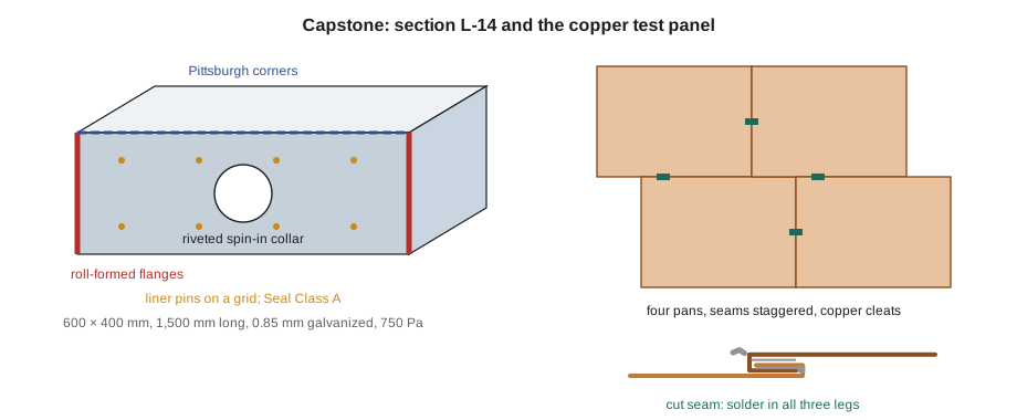
Lin's shop drawing for section L-14 of the library supply main was a straight rectangular section 1,500 mm long, 600 by 400 mm inside the liner, in 0.85 mm galvanized steel, for the 750 Pa pressure class. Its details were:
- Two L-shaped pieces, closed with Pittsburgh locks at two opposite corners, with sealant inside the pockets.
- Roll-formed flange transverse joints at both ends, with corner pieces and gasket, as on the gym mains.
- 25 mm (1 in) acoustic liner on all four inside faces, held with adhesive and capacitor discharge insulation pins at the spacing the standard set for the duct velocity.
- A 250 mm (10 in) round branch takeoff on one side, with a flanged spin-in collar riveted to the duct wall and sealed.
- A hinged access door on the opposite side for the damper downstream, its frame riveted and sealed.
- Seal Class A: every joint, seam and penetration sealed, including the rivets of the collar and door frame.
- A label with the section number, airflow arrow and pressure class.
Kai's first job was to list every joint on the section and match each to the method and the lesson it came from. Aggie called this the joint schedule, and it is the habit she wanted him to take into every job: before cutting anything, know every joint you will make.
| Joint | Type | Method | Sealing | Lesson |
|---|---|---|---|---|
| Corner seams (2) | Longitudinal | Pittsburgh lock, flange into pocket, lip closed | Sealant in pocket, ends closed | 3 |
| Section ends (2) | Transverse | Roll-formed flange, corner pieces | Gasket, corners sealed | 4 |
| Branch collar | Fitting to duct | Flanged spin-in collar, riveted | Mastic over flange and rivets | 5, 7 |
| Access door frame | Fastened | Riveted frame, closed-end rivets | Sealant under frame, over rivets | 7 |
| Liner pins | Stud weld | Capacitor discharge pins with washers | Pin bases sealed outside if required | 10 |
| Penetrations | Various | Screws for label and hanger tabs | Sealed (Seal Class A) | 11 |
Building the section
Kai cut the two L-shaped pieces on the shear from a pattern that included the Pittsburgh allowances from Lesson 3 and the flange allowances for the roll former, checked the blanks for square across their diagonals, and ran the pocket edges through the lockformer after forming a test piece and comparing it with the sample board. He formed the flanges and the L bends on the brake, checking the first flange with a square as Walt required, and ran both ends through the flange roll former.
Before closing the section, he applied the liner adhesive to the flat sheets, laid the liner, and welded the insulation pins through it with the capacitor discharge gun, after bending over a test pin on scrap to check the setting. The pins were laid out on a grid set in from the edges and the transverse joint ends, as Lesson 10 described, and he cut the liner back at the flange ends so it would not be pinched in the joint.
He cut the branch opening and the access door opening with a nibbler, deburred both, and then assembled the section: sealant run into both pockets, the flanges slid fully home along the whole length, and the lips closed with a mallet on a dolly, working evenly from end to end. He checked both corners by thumbnail and by sighting, and measured the diagonals at each end, which agreed within 2 mm (1/16 in). He inserted the corner pieces, riveted the spin-in collar and the access door frame with closed-end rivets over a bead of sealant, and finished the section with mastic over the collar flange, the frame and every rivet head, and with a fillet across the end of each corner seam to close the tunnels.
# Bill of joints and fasteners for one lined section (Keelson planning values)
import math
w, h, L = 0.6, 0.4, 1.5                       # inside duct size and section length, m
pin_edge, pin_s_across, pin_s_along = 0.075, 0.3, 0.4
corner_seam_len = 2 * L                # two Pittsburgh corners
flange_perim = 2 * (w + h)             # one end
gasket = flange_perim                  # one gasket per joint, applied at one end
def pins(side):
    n_a = math.ceil((side - 2 * pin_edge) / pin_s_across) + 1
    n_l = math.ceil((L - 2 * pin_edge) / pin_s_along) + 1
    return n_a * n_l
total_pins = 2 * pins(w) + 2 * pins(h)
collar_rivets = max(3, math.ceil(math.pi * 0.25 / 0.1))   # around the collar flange
door_rivets = 2 * math.ceil(0.4 / 0.1) + 2 * math.ceil(0.3 / 0.1)
print(f"Pittsburgh seam length: {corner_seam_len:.2f} m")
print(f"flange perimeter per end: {flange_perim:.2f} m, gasket per joint: {gasket:.2f} m")
print(f"insulation pins: {total_pins}")
print(f"closed-end rivets: collar {collar_rivets}, door frame {door_rivets}")
seal = corner_seam_len + 2 * flange_perim + math.pi * 0.25 + 2 * (0.4 + 0.3)
print(f"length to seal (seams, flange corners and edges, collar, frame): about {seal:.2f} m")Pittsburgh seam length: 3.00 m flange perimeter per end: 2.00 m, gasket per joint: 2.00 m insulation pins: 50 closed-end rivets: collar 8, door frame 14 length to seal (seams, flange corners and edges, collar, frame): about 9.19 m
The script is the material side of the joint schedule: what to pull from stores before starting. Kai printed it and taped it to the bench, and ticked items off as he used them. When he came to rivet the door frame he found he had pulled open-end rivets from the wrong bin, which the list caught before a single one went in.
Checking the section
Aggie went over the section with Kai using Keelson's checklist, built from the inspection points in each lesson.
- Corner seams: lips flat and tight end to end, flanges fully seated, corners straight, no cracked coating.
- Squareness: diagonals at each end within the shop tolerance.
- Flanges: straight and undamaged, corner pieces fully seated, liner cut back clear of the flange.
- Pins: on the grid, at the required edge distances, a sample bent over without breaking, liner held but not crushed.
- Collar and door frame: rivets closed-end, square and tight, edge distance kept, sealant continuous.
- Sealing: every joint, seam end and penetration covered to the stated thickness, no gaps at corners.
- Label: section number, airflow arrow and pressure class.
Because the library main was going to be leakage tested, and section L-14 was the first lined section with a branch and a door, Walt ran a shop leakage check on it once the mastic had cured: ends blanked off with plates on the flanges, the section pressurized to 750 Pa with the shop's test rig, and the leakage read on the rig's flow meter. The section leaked less than its share of the allowance for the run. A small hiss at one door hinge screw, found with soapy water, was sealed and the test repeated.
# Shop leakage check for one section against its share of the run allowance
CL = 4
area_ft2 = 2 * (0.6 + 0.4) * 1.5 * 10.764                   # duct surface area of the section, ft2
p = 750 / 249.1                           # test pressure, in w.g.
allow = CL * p ** 0.65 * area_ft2 / 100     # cfm for this section
measured = 1.6                   # measured leakage, cfm
print(f"allowance for this section: {allow:.2f} cfm" + f" ({allow * 0.4719:.2f} L/s)")
print(f"measured: {measured:.2f} cfm -> {measured / allow * 100:.0f} percent of allowance, {'pass' if measured <= allow else 'fail'}")allowance for this section: 2.64 cfm (1.25 L/s) measured: 1.60 cfm -> 61 percent of allowance, pass
A single section is a small sample, and the real test happens when the whole run is installed and tested in the field, covered in SMW-310. But a shop check on the first section of a new type catches a bad detail before it is repeated on fifty more, which is what it is for.
The copper panel
The St. Brendan's side aisles were to be re-roofed in flat lock copper, and the architect wanted a test panel made and cut apart before the work started, to see the solder penetration for herself. Aggie gave the job to Kai. The panel was four small flat lock pans of 16 oz copper laid on a plywood test deck, with locks of the width the specification called for, cleated to the deck with copper cleats and copper nails, and soldered with 50/50 solder using two heavy coppers.
His sequence followed Lessons 6 and 8 step by step.
- Cut the pans to the finished size plus a lock allowance on each edge, from a full-size paper template checked against the deck.
- Clean both faces of each lock area to bright copper, wider than the solder would reach.
- Flux and pre-tin the lock areas, front and back, on both pieces.
- Fold the locks on the brake with a slight radius, two edges up and two down.
- Lay the pans from the low edge up, hook the locks and cleats together, stagger the seams so no four corners met, and flatten the seams with a mallet.
- Flux the outside of the seams and sweat them with the copper, feeding solder at the edge and moving steadily until solder showed along the back of each lock.
- Wipe the seams smooth, neutralize the flux residue and rinse.
Then, with the architect watching, Aggie cut three of the seams across with a hacksaw at random points and polished the cut faces. In every cut, solder had filled the outer two legs and reached into the third. On the fourth seam Kai had moved too quickly near the end, and the cut showed the third leg dry for the last 40 mm (1 1/2 in). Nobody was surprised. Aggie had him resolder that seam, cut it again, and show the full penetration, and the architect approved the detail with a note on the speed of the copper.
The records
Keelson's quality system asked for records of both pieces of work. For the duct section, the record was the shop drawing with the joint schedule, the material list, the test coupon results for the pin welder, the leakage check result, and Walt's sign-off on the checklist. For the copper panel, it was the panel's description, the photographs of the cut seams, the corrected seam and the architect's approval note. None of it took long, and all of it was there when the school board's engineer asked, months later, how the library duct had been built and tested.
Records also close the loop on the joints that went wrong. Kai's three leaking joints from the first week at Ashgrove, the wrong rivets caught by the materials list, the dry third leg on the copper seam: each was written up in a line or two in the job log with its cause and fix. Aggie's view was that every joint that fails teaches the whole crew, but only if someone writes it down.
What Kai took from the course
At the end of the course, Aggie asked Kai what he would tell the next first-year apprentice about joints. His list was short.
- Know every joint before you cut: make the joint schedule.
- Check the first one of everything: the first flange, the first test piece, the first pin, the first coupon.
- Seat it fully: flanges in pockets, drives the full length, slip joints all the way home, cleats fully hooked.
- Clean before you seal, flux or solder; most bad joints were dirty first.
- Close the tunnels and seal the corners; that is where the air and water get out.
- Use the right metal and the right fastener; dissimilar metals and the wrong rivet fail later, not now.
- Write down what went wrong, so it does not go wrong twice.
SMW-210 takes Kai back to pattern development, with cones, transitions and triangulation. SMW-220 builds on these joints with the full duct construction standards, reinforcement and pressure classes, and SMW-230 adds arc welding for thin gauge.
Common mistakes
MistakeStarting fabrication without listing the joints.
InsteadMake a joint schedule and a material list before cutting.
MistakeWelding insulation pins without a test pin.
InsteadBend over a test pin on scrap to check the setting first.
MistakeLeaving the liner running into the flange joint.
InsteadCut the liner back so it is not pinched in the joint.
MistakeMoving the soldering copper too fast near the end of a seam.
InsteadKeep an even pace and watch for solder at the back of the lock to the very end.
MistakeFixing a defect without recording it.
InsteadWrite the cause and the fix in the job log.
Summary and key terms
- A joint schedule lists every joint on a part with its method, sealing and source before work starts.
- Section L-14 combined Pittsburgh locks, roll-formed flanges, riveted collar and door frame, insulation pins and Seal Class A sealing.
- First-article checks and a shop leakage test catch a bad detail before it is repeated.
- The copper test panel used cleaned, fluxed and pre-tinned locks, cleats and sweated solder, proved by cutting the seams.
- Records of drawings, tests, checks and defects make the work traceable and teach the crew.
- Seat every joint fully, clean before sealing or soldering, close the tunnels, and write down what went wrong.
- Joint schedule
- A list of every joint on a part with its method, sealing and reference.
- First article check
- Inspecting the first piece made with a new setup before making more.
- Shop leakage check
- A pressure test of a sample section in the shop before the field test.
- Test panel
- A sample of a detail built and examined to prove the method before the job.
- Sign-off
- A recorded approval that a part or detail meets the requirements.
- Job log
- The running record of events, problems and fixes on a job.
Practice problems
Work each problem on paper first, then reveal the answer to check.
Why did Kai make a materials list from the joint schedule?
Show answer
To pull the right parts before starting, which caught the wrong rivets before they were used.
What did the cut seams on the copper panel show?
Show answer
Solder in all three legs on three seams, and a dry third leg near the end of the fourth, which was resoldered.
Why test only the first lined section in the shop?
Show answer
To prove the new detail before it was repeated on many more sections; the full run is tested in the field.
Name three items in the duct section's record.
Show answer
Shop drawing with joint schedule, pin welder test results, leakage check result and the checklist sign-off.
Lesson quiz · 5 questions
Score 60% or more to complete this lesson.
Create a free account to save your progress, take quizzes and earn a certificate.