
SMW-110 · Lesson 12 of 12 · 17 min
The first shop project: a drain pan and drip edge
At the end of Kai's sixth week, Walt handed him a job package with two items on it and his own name in the "fabricated by" box. The first was a condensate drain pan for one of the new rooftop units at Ashgrove Elementary, which the field crew had found needed a deeper pan than the unit maker supplied. The second was a run of copper drip edge for the St. Brendan's Church roof, to match the profile Kai had practised in scrap in Lesson 9. "Same rules as always," Walt said. "Read it, plan it, check it, build it, check it again. Aggie signs it off, not me." This lesson follows that job from package to sign-off and brings together everything in this course.
Reading the job package
The package held a shop drawing of the pan, a work order and a copy of the drip edge profile from the architect's detail. The pan's inside base was to be 900 by 600 mm with 50 mm sides, in 1.31 mm (18 gauge) galvanized steel with Z275 coating, its corners notched, folded and sealed watertight, with a 25 mm drain outlet in one corner. The drip edge was 16 oz copper, in pieces 2,438 mm long, with the four-leg profile from Lesson 9. The work order gave quantities, one pan and twelve drip edge pieces, the job numbers to charge, and the due date: Thursday morning, for the Ashgrove truck.
Kai read the drawing twice and wrote down three questions before he touched a sheet. Were the 50 mm (2 in) sides inside or outside dimensions? The drawing said inside. Did the drain outlet come from stores or did he make it? From stores, a soldered fitting to be fixed with rivets and sealed. And which edge of the drip edge was the hem? The architect's detail showed it on the lower leg. Walt answered all three in a minute. "Better three questions now than one wrong pan on Thursday," he said.
Planning the hazards
Before starting, Keelson's procedure asks for a short written hazard check on any new task. Kai's covered the machines he would use, the shear, the notcher, the box and pan brake and the drill, with their guards and the lockout procedure for clearing jams; the materials, galvanized steel with sharp sheared edges and copper that marks easily; the noise at the shear and notcher; and the handling of a full sheet of 18-gauge steel, which weighs more than 30 kg (65 lb) and is a two-person lift. The controls were the ones this course has covered: cut-resistant gloves for handling sheet but none at the drill press, safety glasses and hearing protection, two-person handling for full sheets, and a clean bench. Aggie read it and added one line: drill the drain hole before bending, while the pan is flat and can be clamped.
Material and layout
Kai pulled a sheet of the right material and checked it, because Lesson 4 had taught him to check the sheet and not the label. The micrometer read 1.30 to 1.32 mm (0.051 to 0.052 in), which matched 18-gauge galvanized. He wiped the mill oil off the layout area, established a reference edge, and laid out the pan blank.
The pan blank is a rectangle with a square notch at each corner. Its length and width are the inside base plus the sides on each end, adjusted for the bends. Because the sides are given as inside dimensions, each side adds its height plus the material thickness, less the bend deduction for a 90-degree bend, which on 18-gauge steel with the brake's nose radius is small but not zero. The corner notches remove the squares that would otherwise overlap when the sides fold up, except for a tab on each corner that is folded around and riveted to seal the corner.
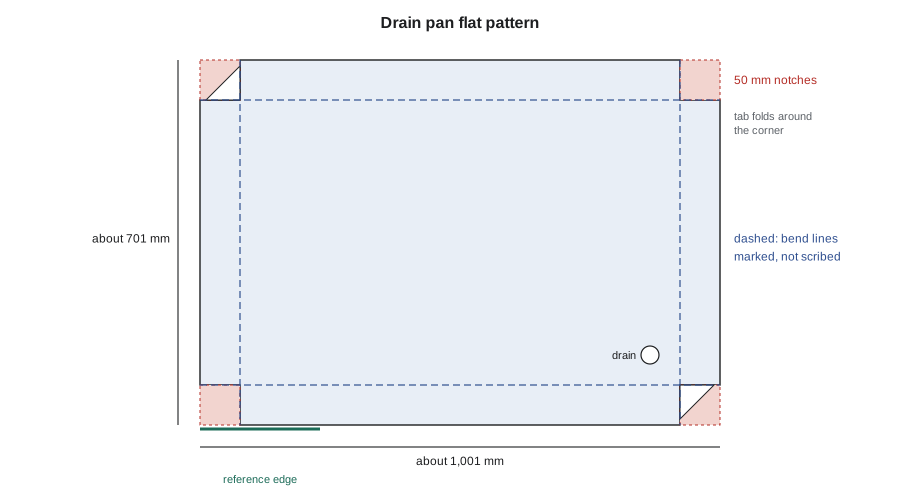
The script works out the blank and the notch sizes from the drawing's inside dimensions, then plans how the twelve drip edge blanks are cut from a full copper sheet.
# Drain pan blank and drip edge cut list
import math
T, R, K = 1.31, 1.5, 0.44   # mm                         # thickness, brake nose radius, K-factor (shop table)
base_l, base_w, side = 900, 600, 50   # mm            # inside base length, width and inside side height
ba = math.pi / 2 * (R + K * T)                      # 90 degree bend allowance
setback = R + T                                     # outside setback of a 90 degree bend
deduction = 2 * setback - ba                        # bend deduction for one bend
blank_l = (base_l + 2 * T) + 2 * (side + T) - 2 * deduction   # outside legs minus two deductions
blank_w = (base_w + 2 * T) + 2 * (side + T) - 2 * deduction
notch = side - R + ba / 2                           # square notch: edge to the middle of the bend
print(f"pan blank {blank_l:.0f} x {blank_w:.0f} mm, corner notches {notch:.0f} mm square")
print(f"weight about {blank_l * blank_w * 1.31 / 1e9 * 7850 * 1.02:.1f} kg")
# Drip edge: twelve pieces from copper sheets, each blank the developed width from Lesson 9
strip, length, pieces = 180.1, 2438, 12   # mm developed width, length, pieces
sheet_w, sheet_l = 914, 2438   # mm copper sheet (36 in by 96 in)
per_sheet = int(sheet_w // strip)
sheets = math.ceil(pieces / per_sheet)
print(f"drip edge blanks {strip} x {length} mm: {per_sheet} per sheet, {sheets} sheets for {pieces} pieces")
print(f"offcut on the last sheet: {sheet_w - (pieces - (sheets - 1) * per_sheet) * strip:.0f} mm wide")pan blank 1001 x 701 mm, corner notches 50 mm square weight about 7.4 kg drip edge blanks 180.1 x 2438 mm: 5 per sheet, 3 sheets for 12 pieces offcut on the last sheet: 554 mm wide
The blank came out at about 1,001 by 701 mm, with 50 mm square corner notches, and weighed about 7.4 kg. The drip edge blanks, at the developed width of about 180 mm calculated in Lesson 9, fitted five to a 914 mm copper sheet, so twelve pieces needed three sheets with a wide offcut on the last one. Walt had Kai mark the offcut with the job number and put it back in the copper crate for the church's later flashings.
Kai scribed the cut lines, which would be cut away, and marked the bend lines with a fine marker, because on galvanized steel a scribed bend line would crack the zinc along the outside of the bend. He checked the layout's diagonals: they matched within 1 mm (1/32 in).
Cutting and notching
At the shear, Kai checked the squaring arm with a square and made a test cut on scrap, then cut the blank to size, keeping his hands in front of the finger guard and his foot off the pedal until they were clear. The corner notches went on the power notcher, set to 90 degrees with its depth stops at the notch size, and he left the tabs on two corners by notching only partway, as the drawing showed. He deburred every edge with a file and a deburring tool, because the pan's edges would be handled by the field crew on a roof.
Before any bending, he drilled the drain outlet hole. The pan was flat and could be clamped to the drill press table, as Aggie had written, and he used a step drill at low speed so the hole came out round and clean in the 18-gauge steel. Then he checked the hole's position against the drawing.
Bending in the right order
The pan was a box and pan brake job, and the order mattered, as Lesson 9 had shown. Kai planned it on paper first. The two long sides would be bent first, with the fingers set across the full length. Then the fingers would be rearranged to just less than the inside length between the two bent-up long sides, and the two short sides bent between them. Finally the corner tabs would be folded around the outside of the long sides by hand with a hand seamer and dressed tight with a mallet over a stake.
He made a quick test bend on a scrap strip of the same material to check springback and found it settled at 88 degrees, so he overbent each side by two degrees. After each bend he checked the angle with a square and the side height with a rule. The first long side came out a millimetre high, within the drawing's tolerance; the others were on. When the short sides came up between the long ones, the corners closed neatly against the tabs.
Fastening, sealing and checking
Each corner tab was drilled and fastened with two blind rivets of the right grip range, in steel to suit the galvanized pan, and the drain fitting was riveted in place. Then Kai sealed the inside of every corner and the joint around the drain fitting with gun-grade mastic, worked into the joint rather than spread over it, as Lesson 11 had taught. The drawing called for a water test, so after the sealant had cured overnight he set the pan level on the bench, plugged the outlet and filled it to 25 mm (1 in) depth. He checked every corner after an hour and found it dry.
The drip edge pieces were simpler but less forgiving. Kai bent them on the cornice brake with a clean nose bar and a soft pad on the clamping bar so the copper would not be marked, in the order he had planned in Lesson 9, and checked the first piece against the architect's profile before running the other eleven. He handled the finished pieces with clean gloves, because fingerprints on new copper show for months.
| Check | Method | Result |
|---|---|---|
| Material and thickness | Micrometer on the sheet | 18-gauge galvanized, as specified |
| Layout square | Diagonals | Within 1 mm (1/32 in) |
| Pan dimensions | Rule and square after bending | Within tolerance; one side 1 mm (1/32 in) high |
| Corner and drain watertightness | Water test after cure | Dry after one hour |
| Drip edge profile | First piece against the detail | Matched; eleven more run |
| Edges | Visual and gloved hand | Deburred; no sharp edges left |
| Paperwork | Work order, hours, logbook | Completed and signed |
Sign-off and clean-up
On Wednesday afternoon, Aggie inspected both items. She checked the pan's dimensions and corners herself, looked inside the corners for skips in the sealant, and ran a gloved hand along every edge. She checked the drip edge profile against the detail with a contour gauge and looked along the length of each piece for twist. Then she signed the "checked by" box. "Good," she said. "Now clean up." Clean-up meant scrap in the scrap bins, sorted by metal so the copper went to its own bin, offcuts labelled and returned, tools back in their places, the brake's fingers put back to their usual arrangement, and the floor swept. The pan went on the Ashgrove truck on Thursday morning, and the drip edge into a crate for the church crew.
Kai filled in his logbook that night: hours on layout, shearing, notching, bending, drilling, riveting, sealing, testing and inspection; the machines used; and Aggie's initials. Six weeks earlier he had not known what a gauge wheel was. He now had his first piece of work in a building, and he had done it without a cut finger.
Looking ahead
This course has covered the trade, its safety practices, its materials and their thicknesses, and the hand tools, power tools and machines of the shop. The rest of the program builds on it. SMW-120 begins pattern development, with the geometry of parallel line patterns for elbows and tees. SMW-130 covers the seams, joints and fastening methods that turn patterns into finished work, including the locks the roll formers make and the soldering the church's copper needs. Later courses take the work into the field: duct fabrication to the industry standards, welding, installation, architectural roofing, balancing, kitchen and industrial exhaust, and estimating. The Ashgrove retrofit, the Brine & Ember hood, the St. Brendan's roof and the Eastgate Hospital wing will follow Kai through all of them.
Common mistakes
MistakeStarting to cut before reading the drawing and asking about unclear dimensions.
InsteadRead the package, list questions, and ask before touching material.
MistakeDrilling holes after a pan is bent, when it cannot be clamped flat.
InsteadDrill holes while the blank is flat and can be clamped.
MistakeBending the sides of a pan in an order that blocks the last bends.
InsteadPlan the sequence and use a finger brake for the sides that fall between existing flanges.
MistakeScribing bend lines on galvanized steel.
InsteadMark bend lines with a fine marker; scribed lines crack the zinc on the outside of the bend.
MistakeTreating the job as finished when the last bend is made.
InsteadInspect, test, document, clean up and log the hours before calling it done.
Summary and key terms
- A job begins with reading the package and asking questions before cutting.
- A short hazard check identifies machines, materials, noise and handling risks and their controls.
- Check the material, lay out from a reference edge, verify square by diagonals and calculate blanks with bend deductions.
- Cut, notch, deburr and drill while the blank is flat; then bend in a planned order, allowing for springback.
- Fasten with matching fasteners, seal properly, and test what the drawing requires.
- Inspection, sign-off, clean-up and the logbook complete the job.
- Job package
- The drawings, work order and details issued for a piece of work.
- Hazard check
- A short written review of the hazards of a task and their controls before starting.
- Corner tab
- A part of a pan or box blank left uncut at a notch, folded around the corner and fastened.
- Water test
- Filling a pan or tray with water to check that its seams and corners do not leak.
- Sign-off
- The inspection and signature of a qualified worker confirming that work meets the drawing.
Practice problems
Work each problem on paper first, then reveal the answer to check.
A pan has an inside base of 800 by 500 mm and 40 mm inside sides in 1.00 mm steel. Ignoring bend deductions, about what blank size is needed?
Show answer
About 802 + 2 × 41 by 502 + 2 × 41, or 884 by 584 mm, before subtracting the small bend deductions.
Why was the drain hole drilled before bending?
Show answer
The flat blank could be clamped safely to the drill press table.
Copper drip edge blanks are 180 mm wide. How many fit across a 914 mm sheet?
Show answer
Five, with a 14 mm offcut.
What checks did Aggie make before signing off?
Show answer
Dimensions, corners and sealant, edges, the drip edge profile and twist.
Lesson quiz · 5 questions
Score 60% or more to complete this lesson.
Create a free account to save your progress, take quizzes and earn a certificate.