
ROOF-320 · Lesson 11 of 12 · 21 min
Reading roofing detail drawings
▶ Video coming soon A video version of this lesson is on the way.
On the Saturday morning of the Northgate review, Martin Oyelaran unrolled eleven sheets of draft drawings across the big table in Ridgecap's office. Glen took the roof plan and the drainage sheet. Martin gave Rory the detail sheets, three of them, each with a dozen numbered details, and a highlighter. "Read every detail as if you had to build it on Monday," he said. "Mark anything you can't build, anything that doesn't match the maker's standard detail, and anything you don't understand. If you don't understand it, the crew won't either." Rory found nine things by noon. Two of them were mistakes in the drawings.
This lesson covers how roofing work is shown on construction drawings and specifications: how a set of drawings is organized, roof plans and their symbols, detail callouts and section marks, scales and dimensions, notes and keynotes, how details relate to the specification and the maker's standard details, and what to do when the drawings do not work. The skill is the same for a new building, a re-roof and a repair.
How a set of drawings is organized
Construction drawings come in sets, divided by discipline: architectural (A), structural (S), mechanical (M), electrical (E), plumbing (P) and sometimes a separate roofing set prepared by a roof consultant. On a re-roof like Northgate, the roof consultant's set may be the only drawings. Each sheet has a title block with the project, the sheet number, the date, the revision and the drawing scale or scales. The roofer usually needs:
- The roof plan, showing the outline of the roof, slopes, drains, crickets, curbs, penetrations, expansion joints, walkways, and where each detail applies.
- Building sections and wall sections, showing how the roof meets the walls and parapets in height.
- Detail sheets, showing each edge, flashing, curb and penetration at a large scale.
- The structural drawings, for the deck type, deck direction, joist locations, support steel and any loads the roof work affects.
- Mechanical and plumbing drawings, for curbs, equipment, vents, gas lines and drains.
- The specification, the written part of the contract documents, which describes the materials, standards, methods, quality, testing and warranties.
Drawings show where things go and how they fit; specifications say what they are made of and how well they must be done. When the two disagree, the contract usually says which governs, often the specification for materials and quality, and the drawings for location and quantity. When in doubt, ask.
Roof plans
A roof plan is a view from directly above. It shows the outline of the roof and every feature on it, with slope arrows pointing downhill and the amount of slope written beside them, drains with their elevations, the ridges and valleys of tapered insulation and crickets, high and low points, curbs and units with their sizes and identification tags, penetrations, hatches, skylights, walkways and fall protection anchors. Tapered roofs often have a separate tapered insulation plan from the insulation maker, with panel layouts and thicknesses.
The roof plan also tells you where the details are. A detail callout on the plan, usually a circle divided by a line, points to a place on the roof and says which detail applies there: the number in the top half is the detail number, and the number in the bottom half is the sheet it is drawn on. A callout marked 5 over R-501 means detail 5 on sheet R-501. A section mark looks similar but has an arrow or a flag showing which way the section looks.
Details and sections
A detail is a large-scale drawing of one small part of the roof, usually a section cut through it. Detail drawings show each layer, its material, its thickness or size, how it is fastened and in what order the layers go on. Materials are shown by hatching patterns: wood with a grain or a cross, insulation with a wavy or cross-hatched pattern, concrete with dots and small triangles, steel deck as a thick fluted line, membrane as a heavy line. Leader lines with arrows point from notes to the layer they describe.
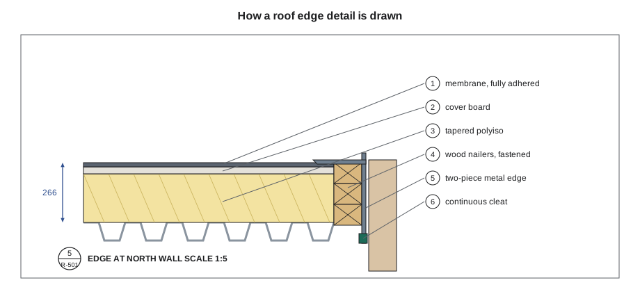
Many details are marked typical, which means they apply wherever the same condition occurs on the roof, not just at the one place shown. A typical parapet detail applies to every parapet unless another detail is called out. Where a condition differs, such as a parapet that is lower at one end, the typical detail may not work, and the roofer must ask how to build it.
Scales and dimensions
Details are drawn to scale, a fixed ratio between the size on paper and the real size. Canadian drawings use metric ratios: 1:5 or 1:10 for details, 1:100 or 1:200 for roof plans. A 1:5 scale means 1 mm on the drawing is 5 mm on the roof. Some details are marked NTS, not to scale, and must be built from their written dimensions only.
Written dimensions always govern over measuring the drawing. Measure only when there is no dimension, and treat the result as approximate; drawings are often printed at a different size from the one they were drawn at. A printed graphic scale bar, if there is one, will shrink and grow with the print and can be trusted where a written ratio cannot.
Worked problem
Measuring from a detail
Martin's detail 5 on sheet R-501 is drawn at 1:5. Rory measures the nailer stack on the printed sheet as 53 mm high, and the overlap of the fascia on the wall below as 15 mm. The graphic scale bar on the sheet, marked 0 to 500 mm, measures 100 mm long on the print. What are the real sizes, and is the print true to scale?
Show solution
- Check the print: 500 mm real ÷ 100 mm on paper = 5, which matches 1:5, so the print is true to scale.
- Nailer stack = 53 × 5 = 265 mm, which agrees with the 266 mm written on the section.
- Fascia overlap = 15 × 5 = 75 mm.
- Use the written 266 mm, not the measured 265 mm.
Answer: The print is true; the stack is 266 mm as written and the fascia laps the wall by about 75 mm. If the scale bar had measured 80 mm, the print would have been reduced, and every measurement would read 20 in 100 short.
Notes, keynotes and the specification
Drawings carry three kinds of text. General notes, usually on the first sheet, apply to the whole job: which code edition, which standards, the membrane maker and system, the warranty, the order of work. Keynotes are numbered or lettered tags on a detail that point to a list of descriptions, so the same material can be named the same way on every detail. Specific notes are written right on a detail.
The specification is organized in sections, usually following the MasterFormat numbering used across North America. Roofers work mostly in Division 07, thermal and moisture protection: sections for the membrane roofing system, sheet metal flashing and trim, roof specialties and accessories such as hatches, curbs and edge systems, and joint sealants. Other sections cover the deck, the wood blocking, the drains and the equipment curbs. A keynote on a detail often gives the specification section number, so the reader can find exactly which product and standard applies.
| Where to look | What you find there |
|---|---|
| Roof plan | Slopes, drains, crickets, curbs, penetrations, joints, walkways and detail callouts |
| Detail sheet | Layers, materials, fastening, dimensions and order of each flashing and edge |
| General notes | Code edition, standards, membrane system, warranty and sequence |
| Specification Division 07 | Membrane, sheet metal, accessories and sealant products, standards and methods |
| Structural drawings | Deck type and direction, joists, support steel and openings |
| Maker's standard details | The details the membrane maker will warrant, which the drawings must not contradict |
When the drawings do not work
Drawings are made by people, often in a hurry, and roofing details are frequently copied from other jobs. Common problems include a typical detail that does not fit a particular condition, a flashing height that cannot be reached because the wall is too low, a detail that contradicts the membrane maker's requirements and would void the warranty, layers drawn in an order that cannot be built, dissimilar metals touching, an expansion joint that stops at a wall with no detail for the turn, and mechanical drawings that put a curb too close to a parapet. A detail that does not work must not be built as drawn and must not be quietly changed in the field. It is raised in writing.
On most projects the written question is a request for information, an RFI, sent through the general contractor to the designer, describing the problem, the location, the drawing and detail numbers, and if possible a proposed answer with a sketch. The designer's written answer becomes part of the contract. Before the work starts, the roofer also prepares submittals: product data, the maker's details, and shop drawings for sheet metal showing every profile, girth, gauge, joint and fastener. The designer reviews them before anything is fabricated. Theo's coping shop drawings for Parkdale went to Hugo Maranda, the arena's facilities manager, for approval before he cut a single piece.
Rory's nine marks
At the Northgate review Rory's highlighter found nine items. Four were questions about the order of work at the edge, which Martin answered on the spot. Two were places where the typical curb detail showed a curb height of 300 mm above the deck rather than above the finished roof; Martin agreed that the note should say above the finished roof, and changed it. One was a coping joint shown sealed solid with no cover plate, which Martin changed to a back plate and cover plate joint. One was the hatch, which had no cricket on the drawings, although the plan showed water running toward it; Martin added one. The last was the air barrier at the north wall, already on Ridgecap's review list. "That's what reading a drawing means," Glen said afterwards. "Not looking at it. Building it in your head." The revised drawings are planned for the budget set in December.
Reading a detail, step by step
Martin's advice to read every detail as if you had to build it on Monday comes down to a routine Rory now uses on every detail sheet.
- Find where it applies. Go back to the roof plan and find every callout for this detail. Count them, so you know how many times you will build it, and look for places where the condition is different.
- Start at the structure. Identify the deck, the wall and what supports each. Ask whether they can move differently, and whether the detail allows for it.
- Build it upward in order. Name each layer from the deck up, in the order the crew will install it: barrier, insulation, nailers, cover board, membrane, flashing plies, metal. If a layer would have to go on before something that sits under it, the detail cannot be built as drawn.
- Check the water path. Trace a drop of rain from the top of the detail to the field. It must pass over every lap, never into one.
- Check the air path. Trace the air barrier from the roof to the wall. It must be continuous.
- Check heights and laps against the minimums: base flashing height above the finished roof, counterflashing lap, membrane lap onto the field, coping lap over the wall.
- Check materials against the specification and the maker's details, and metals against each other.
- Write down what is missing: fastener types and spacing, corner treatment, the end of the detail where it meets the next one.
Sketches and as-built records
Roofers also make drawings. A quick sketch in a notebook or on the back of a cut-off, with dimensions, is often the clearest way to ask Theo for a piece of metal or to explain a problem to a designer. Photos with a tape measure in the shot do the same job. At the end of a job, Ridgecap marks up a set of drawings with what was actually built, including any changes made by RFI, the locations of hidden items such as abandoned curbs that were decked over, and the products used. That as-built set goes in the owner's file and in Ridgecap's, and it is the first thing anybody reaches for when the roof leaks ten years later.
Common mistakes
MistakeScaling a dimension off a print when a written dimension is shown.
InsteadAlways use the written dimension; measure only when there is none, and check the scale bar first.
MistakeApplying a typical detail to a condition it does not fit.
InsteadAsk how to build it with an RFI.
MistakeBuilding a detail that contradicts the maker's requirements.
InsteadRaise it before work starts; the maker's details govern the warranty.
MistakeChanging a detail in the field without telling anyone.
InsteadPut the change in writing and get the designer's answer.
MistakeFabricating sheet metal before shop drawings are reviewed.
InsteadSubmit shop drawings and wait for review.
Summary and key terms
- A set of drawings is divided by discipline; roofers need the roof plan, sections, details, structural and mechanical sheets and the specification.
- Roof plans show slopes, drains, crickets, equipment and detail callouts that point to a detail number and sheet.
- Details are large-scale sections showing each layer, its material, fastening and order, with hatching, leaders and keynotes.
- Written dimensions govern; check the scale bar before measuring a print.
- Specifications, mostly Division 07 for roofing, define products, standards and methods; keynotes link the two.
- When a detail does not work, raise an RFI; prepare and submit shop drawings before fabricating.
- Roof plan
- A drawing of the roof seen from above, showing its outline, slopes and features.
- Detail
- A large-scale drawing of one small part of the work, usually a section.
- Detail callout
- A symbol on a plan or section that names a detail number and the sheet it is on.
- Keynote
- A numbered tag on a drawing that refers to a list of standard descriptions.
- Specification
- The written part of the contract documents describing materials, standards and methods.
- RFI
- A request for information: a written question to the designer about the drawings.
- Shop drawing
- A drawing made by the contractor or fabricator showing exactly how a part will be made.
- NTS
- Not to scale; the drawing must be built from its written dimensions only.
Practice problems
Work each problem on paper first, then reveal the answer to check.
A callout reads 3 over R-502. What does it mean?
Show answer
Detail 3 on sheet R-502.
At 1:10, a line measures 28 mm on the print. What is the real length?
Show answer
280 mm.
Which governs: a written dimension or a measured one?
Show answer
The written dimension.
Which MasterFormat division covers roofing and sheet metal flashing?
Show answer
Division 07.
What should you do if a typical detail does not fit a condition?
Show answer
Raise an RFI before building it.
Lesson quiz · 5 questions
Score 60% or more to complete this lesson.
Create a free account to save your progress, take quizzes and earn a certificate.