
RCDD-114 · Lesson 8 of 12 · 22 min
Distributed building services and PoE lighting
▶ Video coming soon A video version of this lesson is on the way.
The lighting designer for the college floors has an idea that makes Priya Raman, the electrical engineer, sit up in her chair. 'What if we power the classroom and office lights over Ethernet?' he asks. 'Each fixture gets a network cable, a sensor and an address. No line-voltage branch circuits in the ceilings, no separate lighting control wiring, and the building automation system can see every fixture.' Priya's first question is about heat. Marcus Feld's is about cost. Roz's is about the telecommunications rooms. 'If we do this,' she says, 'we are putting a few hundred more powered cables and several kilowatts of load into our rooms. Let's work out what that means before anyone promises it.'
Distributed building services is a broad name for the trend of delivering both data and power to building devices over communications cabling. Power over Ethernet is the best-known example, and it has grown from powering phones to powering access points, cameras, displays, building automation controllers and even lighting. Related technologies include USB-C power delivery at work areas and fault-managed power systems that carry higher power safely over longer distances. These changes move power distribution, once purely the electrical engineer's domain, into the ICT infrastructure. The RCDD must understand the power levels involved, the heating of cables, the code rules that apply and the effect on telecommunications rooms.
PoE types and power classes
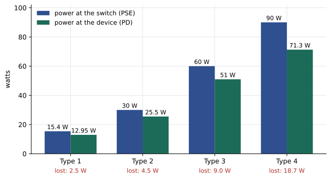
The IEEE 802.3 standards define how power is delivered over balanced cabling and how much. Power sourcing equipment, or PSE, usually a switch, supplies power; the powered device, or PD, receives it. The power available at the device is less than the power supplied, because some is lost as heat in the cabling. Each type has a maximum power at the PSE and a lower guaranteed power at the PD, designed around a 100 m channel. Higher types use all four pairs and higher currents.
| IEEE type | Common name | Pairs used | Power at PSE (about) | Power at PD (about) |
|---|---|---|---|---|
| Type 1 | PoE (802.3af) | 2 | 15.4 W | 13 W |
| Type 2 | PoE+ (802.3at) | 2 | 30 W | 25.5 W |
| Type 3 | 4PPoE (802.3bt) | 2 or 4 | 60 W | 51 W |
| Type 4 | 4PPoE (802.3bt) | 4 | 90 W | 71 W |
The difference between PSE and PD power is the allowance for cable loss. That allowance is large at higher types: for Type 4, almost a fifth of the supplied power can be lost in a long channel. The lost power becomes heat in the conductors, which matters for the cable itself and for the bundle it sits in.
Why cables get warm
Current flowing through a conductor's resistance dissipates power as heat, following P = I²R. Doubling the current quadruples the heat. In a single cable in open air, the heat escapes easily and the temperature rise is small. In a large bundle, especially in an enclosed pathway or insulated ceiling, cables in the middle cannot shed heat and their temperature rises. Higher temperature raises conductor resistance and insertion loss, which reduces transmission performance, and can exceed the cable's temperature rating. This is why PoE guidance pays so much attention to bundle size, conductor gauge and installation conditions.
Worked problem
Loss in a Type 3 channel
A Type 3 PoE light fixture draws 1.2 A in total from the switch over a four-pair channel. The effective DC resistance of the channel for the powered circuit is 6.25 ohms. How much power is dissipated in the cable, and what fraction of a 60 W supply is that?
Show solution
- Power lost: P = I²R = 1.2² × 6.25 = 1.44 × 6.25 = 9.0 W.
- Fraction of supply: 9.0 ÷ 60 = 0.15.
Answer: About 9 W, or 15 hundredths of the supply. That matches the difference between 60 W at the switch and 51 W at the device for Type 3. Shorter channels and larger conductors lose less.
Three practical rules follow. First, larger conductors have lower resistance, so Category 6A cable with 23 AWG conductors heats less than thinner cable for the same current. Second, smaller bundles and open pathways such as cable tray or J-hooks shed heat better than large bundles in conduit or enclosed spaces. Third, temperature ratings and derating rules from the cabling standards must be applied, because performance and length limits assume certain conditions. TIA guidance on supporting remote powering, including its bulletin on bundle sizes, and manufacturer data give the details.
Code rules for power over communications cabling
In Canada, the Canadian Electrical Code addresses low-power circuits such as Class 2 circuits and communications circuits that carry power. Recent editions have added requirements recognizing power over communications cabling, and some cable products carry markings for limited-power use. The designer must check the requirements of the edition adopted in the province, coordinate with the electrical engineer and follow manufacturer installation limits for bundles that carry PoE.
In both countries the electrical code governs safety, while the cabling standards and manufacturer data govern performance. A bundle that meets the code may still lose too much transmission performance if it runs hot, and a channel that performs well on day one may not do so after many PoE devices are added. The RCDD's design should state the PoE type expected at each location, the maximum bundle sizes and the pathway types, so that installers do not create hot bundles by accident.
PoE lighting
PoE lighting systems power LED fixtures from network switches or from dedicated lighting nodes that combine PoE outputs with control software. Each fixture or group of fixtures has its own cable, and often its own occupancy and daylight sensor. Benefits include low-voltage installation in the ceiling, fine-grained control and data on occupancy and energy use for each fixture. Drawbacks include the number of cables, the PoE load and heat in telecommunications rooms, dependence on network equipment for lighting and the need for careful coordination with electrical codes for emergency lighting, which usually must remain on separate, code-compliant systems unless the PoE system is specifically listed and approved for that use.
Worked problem
How much power does the lighting add?
The second-floor college wing has 2,400 m² of space. The lighting designer expects about 6 W of LED lighting per square metre. If the lights are powered by PoE switches with a 15 hundredths average allowance for cable loss and switch inefficiency on top of the fixture load, how much PoE capacity do the switches need?
Show solution
- Fixture load: 2,400 × 6 = 14,400 W, or 14.4 kW.
- With the allowance: 14.4 × 1.15 ≈ 16.6 kW.
Answer: About 16.6 kW of PoE capacity for lighting on one wing, far more than the access points, cameras and building automation combined. That load needs dedicated switches or lighting nodes, power circuits, cooling and possibly a dedicated room.
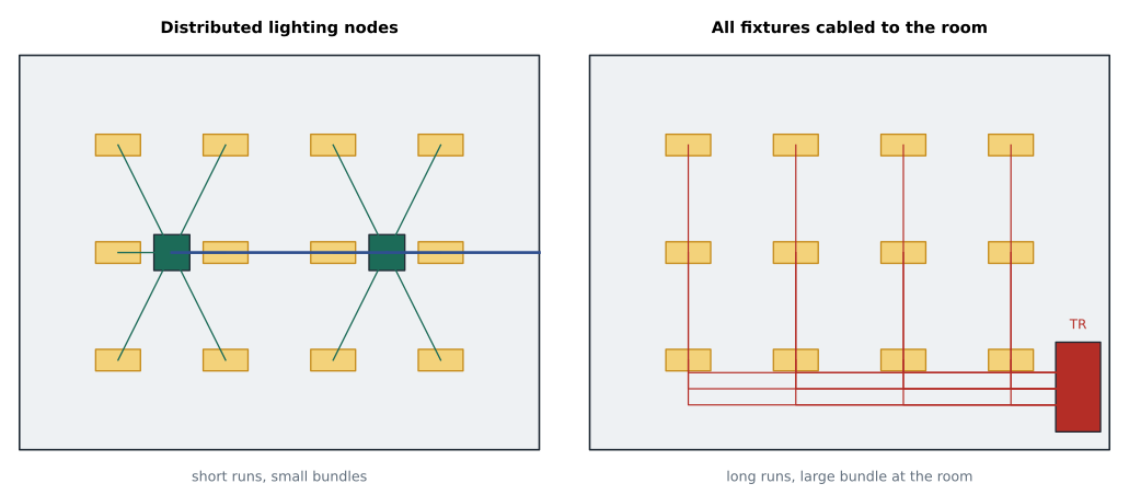
Daniel compares the result with his other PoE loads on the floor: about 540 W for access points, 219 W for lecture hall AV and a few hundred watts for building automation. Lighting is more than ten times larger than everything else combined. If it is powered from the telecommunications rooms, those rooms would need much larger power feeds and cooling, and the switches powering lighting would become part of the building's critical infrastructure. Many PoE lighting designs therefore use distributed lighting nodes in the ceiling or in small electrical closets close to the fixtures, rather than switches in the main telecommunications room.
USB-C and work area power
Power delivery is also changing at desks and in classrooms. USB-C ports can deliver tens of watts to laptops and other devices, and some furniture and outlet products supply USB-C power fed by PoE or by low-voltage distribution. For the RCDD, these products add more PoE load and more outlets at work areas, and they may change how many electrical receptacles the electrical engineer provides. Their adoption varies widely by owner, so the design basis should state whether they are planned.
Fault-managed power and other approaches
For loads that exceed PoE limits or need longer distances, newer approaches deliver power in packets that are continuously monitored for faults, shutting off within milliseconds if a person or object contacts the conductors. These fault-managed power systems can deliver hundreds of watts over long distances on cable similar to communications cable. Recent Canadian Electrical Code editions and provincial adoptions should be checked for how they treat these systems. They are new in commercial buildings, but they illustrate the direction of the industry: power and data are increasingly delivered together by systems that sit between traditional electrical and communications designs.
Effects on telecommunications rooms
Every watt delivered over PoE comes from a power supply in a switch, and every watt lost in the switch and cabling becomes heat. A telecommunications room that powers access points, cameras and building automation may need two or three kilowatts of PoE. One that also powers lighting could need ten or more. That load drives the room's electrical service, the number and size of UPS units, the cooling capacity, and the space for switches with large power supplies. It also changes how the room must be maintained: a failed switch power supply can now darken a floor or unlock a door.
Worked problem
Heat in the room
The third-floor telecommunications room will hold switches delivering 2,600 W of PoE. The switches themselves consume another 400 W, and the owner assumes about 30 of every 100 watts of PoE is turned into heat inside the room by the switch power supplies rather than delivered down the cables. Roughly how much heat must the room's cooling remove?
Show solution
- Switch consumption: 400 W, all turned into heat in the room.
- PoE conversion heat in the room: 2,600 × 0.30 = 780 W.
- Total heat in the room: 400 + 780 = 1,180 W.
Answer: About 1.2 kW of heat, plus heat from UPS units and other equipment. Daniel passes this figure to the mechanical engineer so that the room cooling can be sized. The rest of the PoE power becomes heat at the devices and along the cables throughout the floor.
Exam focus: PoE and remote powering
Expect exam questions on PoE to test the IEEE types and their approximate power at the switch and at the device, the reason for the difference, and the factors that affect cable heating. Remember the pattern: about 15 W, 30 W, 60 W and 90 W at the switch for Types 1 to 4, with less at the device because of loss in the cabling. If a question gives a current and a resistance, the loss is I²R. If it asks how to reduce temperature rise in a bundle, the answers are larger conductors, smaller bundles, open pathways and attention to ambient temperature.
Questions may also ask which rules apply. The electrical code governs safety, including limits on current per conductor in bundles, and the cabling standards and manufacturer data govern transmission performance. A design that meets one does not automatically meet the other, so the best answer usually involves both.
Common mistakes
MistakeAssuming PoE devices receive the full power the switch supplies.
InsteadPower is lost in the cabling. Use the power available at the device for device design and the PSE power for switch and room design.
MistakeRunning large PoE bundles in enclosed pathways without checking limits.
InsteadLarge bundles heat up. Apply code limits, cabling guidance and manufacturer data for bundle sizes and pathway types.
MistakeTreating PoE lighting as a small additional load.
InsteadLighting can exceed all other PoE loads combined. Plan dedicated equipment, power, cooling and coordination with emergency lighting.
MistakeIgnoring heat from switch power supplies.
InsteadSwitches and PoE conversion create heat in the room. Give the mechanical engineer real numbers.
Summary and key terms
- PoE types range from about 15 W at the switch for Type 1 to about 90 W for Type 4, with less available at the device because of cable loss.
- Cable heating follows P = I²R; larger conductors, smaller bundles and open pathways keep PoE cables cooler.
- Electrical codes govern PoE safety; cabling standards and manufacturer data govern performance under heat.
- PoE lighting can add very large loads, so it often uses distributed nodes rather than central telecommunications rooms.
- USB-C power and fault-managed power extend the trend of delivering power and data together.
- Power sourcing equipment (PSE)
- The device, usually a switch, that supplies PoE power.
- Powered device (PD)
- The device that receives power over the cabling.
- Four-pair PoE
- PoE delivered over all four pairs of a balanced cable, as in IEEE 802.3bt Types 3 and 4.
- LP cable
- Cable marked as limited power and rated for a stated current per conductor.
- PoE lighting node
- A device that supplies PoE to lighting fixtures, often located close to the fixtures it serves.
- Fault-managed power
- A power distribution method that monitors the circuit continuously and shuts off quickly when a fault is detected.
Practice problems
Work each problem on paper first, then reveal the answer to check.
A cable carries 0.8 A with an effective resistance of 6.25 ohms. How much power is dissipated?
Show answer
0.8² × 6.25 = 4.0 W.
About how much power is available at the device for Type 2 PoE?
Show answer
About 25.5 W.
Why might PoE lighting use distributed nodes?
Show answer
To keep runs short, reduce bundle heating and avoid concentrating very large loads and heat in the telecommunications room.
Lesson quiz · 5 questions
Score 60% or more to complete this lesson.
Create a free account to save your progress, take quizzes and earn a certificate.