
RCDD-114 · Lesson 1 of 12 · 25 min
Wireless LAN design principles
▶ Video coming soon A video version of this lesson is on the way.
Three weeks into the Harbourview Health and Learning Centre project, Daniel Oyelaran has finished his horizontal cabling layouts for the clinic floors and the college classrooms. He is proud of them: every workstation has its outlets, every telecommunications room serves its floor within distance limits, and the backbone is sized with room to grow. Then Roz Achterberg drops a printout on his desk. It is a page from the college's information technology standard, and one line is highlighted: 'Wireless is the primary network for students and staff. Wired connections are provided where required.' Roz taps the line. 'Most of the people in this building will never plug into one of your outlets,' she says. 'They will connect to an access point that you have to feed, power, mount and protect. If we get the wireless infrastructure wrong, nobody will care how good the rest of the cabling is.'
This course moves beyond the structured cabling at the heart of an ICT design to the systems that ride on it, or beside it: wireless networks, cellular and public safety radio, audiovisual systems, security, building automation, lighting and the special demands of hospitals, schools, multi-tenant buildings and homes. An RCDD is rarely the specialist who designs each of these systems in detail. The RCDD is the person who makes sure each one gets the cabling, pathways, spaces, power and bonding it needs, and that the systems do not trip over one another. This first lesson starts with the system that touches the most users: the wireless LAN.
What the cabling designer owns in a wireless network
A wireless LAN, or WLAN, is a set of access points connected by cabling to switches, controllers and the rest of the network. The radio part of the design, such as channel plans, transmit power settings and the choice of access point model, normally belongs to a wireless specialist or the owner's network team. The infrastructure part belongs to the ICT designer. That includes the horizontal cabling to each access point location, the outlet and mounting arrangement, the power delivered over the cabling, the capacity of the switch and telecommunications room that feed it, and the flexibility to move or add access points later. A wireless network is only as good as the wired network behind it.
Daniel's first instinct is to ask the wireless team for a list of access point locations and simply run cable to each one. Roz explains why that is not enough. Access point locations are the output of a predictive model that will be checked and adjusted after a site survey, and adjusted again as the building fills with people and furniture. A design that serves only the first set of locations will need new cable runs within a year. The RCDD's job is to design infrastructure that supports the wireless design of today and the likely changes of tomorrow, and to know enough radio fundamentals to judge whether a proposed change is reasonable.
Coverage, capacity and the cell
Each access point serves a cell, the area in which client devices can connect at an acceptable signal level. Two very different questions drive how many cells a building needs. The first is coverage: is the signal strong enough everywhere users need it? The second is capacity: can the access points in each area handle the number of devices and the traffic they generate? In older designs coverage dominated, and access points were spread as far apart as the signal allowed. In modern buildings, especially schools, clinics and offices with many devices per person, capacity usually decides the count. A lecture room with 80 students, each carrying a laptop and a phone, may need its own access point even though one access point in the corridor could cover it with a usable signal.
Designers usually express coverage as a target received signal strength, such as −67 dBm for voice and real-time video, measured at the client device on the chosen frequency band. They also set a minimum signal-to-noise ratio, because a strong signal buried in interference is no better than a weak one. Capacity is expressed as a number of devices per access point radio and an expected throughput per device. Both targets come from the owner's requirements and the applications the network must support. When Daniel reads the college's standard, he finds both: −65 dBm on the 5 GHz band in teaching spaces and 'design for two devices per occupant'.
Frequency bands and channels
Wireless LANs operate in unlicensed bands around 2.4 GHz, 5 GHz and, in newer equipment, 6 GHz. The 2.4 GHz band travels farther and penetrates walls better, but it has only three non-overlapping 20 MHz channels in North America and is crowded with older devices, Bluetooth and microwave ovens. The 5 GHz band offers many more channels and less interference but shorter range. The 6 GHz band, opened for low-power indoor use by Innovation, Science and Economic Development Canada in recent years, adds a large block of clean spectrum that only newer devices can use. Each band has its own regulatory power limits, which is why equipment specifications are given as maximum power under the rules of a particular country.
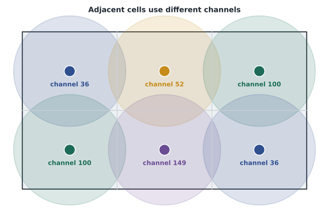
Neighbouring access points on the same channel share the airtime, a problem called co-channel interference. A good channel plan gives adjacent cells different channels so that each can transmit freely. With only three channels at 2.4 GHz, dense deployments often switch off some 2.4 GHz radios entirely. Wider channels, such as 40, 80 or 160 MHz at 5 and 6 GHz, raise the peak data rate of each cell but reduce the number of non-overlapping channels available. These trade-offs belong to the wireless designer, but the RCDD needs to understand them, because they explain why a wireless specialist might ask for more access points, closer together and at lower power, rather than fewer at high power.
| Band | Main strengths | Main limitations | Typical role |
|---|---|---|---|
| 2.4 GHz | Longest range, best wall penetration, supported by almost every device | Few non-overlapping channels; crowded with other devices | Legacy devices, some building sensors and IoT |
| 5 GHz | Many channels, higher capacity, less congestion | Shorter range; some channels require radar detection | Main band for laptops, phones and voice |
| 6 GHz | Large block of clean spectrum, wide channels | Newest devices only; shortest range of the three | High-density and high-throughput areas |
Estimating how many access points a space needs
Before a predictive model exists, a designer often needs a first estimate of access point count to size switches, telecommunications rooms and power budgets. The estimate is made twice, once for coverage and once for capacity, and the larger number wins. Coverage estimates divide the area by a typical cell area for the building type and band. Capacity estimates divide the expected number of devices by the number each access point can serve well. Neither number replaces a proper wireless design, but together they give a sound basis for infrastructure sizing.
Worked problem
The second-floor college wing
The college wing on the second floor of Harbourview has 2,400 m² of classrooms and study space. The wireless team suggests a coverage cell of about 200 m² per access point at 5 GHz in this kind of construction. Peak occupancy is 450 people, the college designs for two devices per person, and each access point is planned for about 50 active devices. How many access points should Daniel plan for?
Show solution
- Coverage: 2,400 ÷ 200 = 12 access points.
- Devices: 450 × 2 = 900 devices.
- Capacity: 900 ÷ 50 = 18 access points.
- The capacity estimate is larger, so it governs: plan for 18 access points.
Answer: About 18 access points, set by capacity rather than coverage. Daniel should size the horizontal cabling, switch ports and power budget for at least that number, plus spare locations.
Roz points out one more consideration. Capacity is rarely spread evenly. A 120-seat lecture hall might need three access points by itself while the corridors outside need very few. Dividing totals across the whole floor gives the right number for the switch room but not the right locations, so Daniel should mark the high-density rooms separately and ask the wireless designer to confirm them.
Signal strength along the path
A wireless link has a budget just like a fibre link. The access point transmits at some power, the antenna adds gain, and the signal loses strength over distance and through walls, people and furniture before it reaches the client. The designer compares the received level with the target to see whether the cell will work. Free-space path loss, introduced in the transmission principles course, gives the loss in open air. Inside buildings, each wall adds more loss depending on its material: a plasterboard partition may cost only a few decibels, while a concrete block wall or an elevator shaft can cost far more.
Worked problem
Will the clinic corridor reach the target?
An access point in a clinic corridor has an EIRP of 20 dBm on a 5,500 MHz channel. An exam room is 12 m away behind one plasterboard wall that the survey team estimates at 5 dB. Using free-space path loss FSPL = 20 log10(d) + 20 log10(f) − 27.55, with d in metres and f in MHz, what signal level reaches the exam room, and does it meet a −67 dBm target?
Show solution
- 20 log10(12) ≈ 21.6 dB.
- 20 log10(5,500) ≈ 74.8 dB.
- FSPL ≈ 21.6 + 74.8 − 27.55 ≈ 68.9 dB.
- Received level ≈ 20 − 68.9 − 5 ≈ −53.9 dBm.
- This is about 13 dB stronger than −67 dBm, so the target is met with margin.
Answer: About −54 dBm, comfortably above the −67 dBm target. In real rooms, people, furniture and multipath reduce the margin, which is why surveys and design tools use measured wall losses.
Calculations like this explain a common request from wireless designers: an access point inside a room with heavy walls rather than in the corridor outside. Imaging suites with shielded walls, stairwells, elevator lobbies and rooms with concrete partitions are frequent examples. Daniel marks these on his plans so that the wireless team can confirm whether each needs its own access point.
Cabling and mounting for access points
The infrastructure for an access point starts with its horizontal cabling. Current practice, reflected in TIA guidance on cabling for wireless access points, is to run Category 6A or better balanced cabling to each location, because access points with multi-gigabit uplinks and high power over Ethernet demand both bandwidth and good heat performance. Many owners, including the Harbourview owner, now run two cables to each location: one for the current access point's uplink and power, and a second to support future access points with dual uplinks or a separate sensor or camera. The cost of a second cable at installation is small compared with adding it later above a finished ceiling.
TIA guidance also describes a grid approach for buildings where access point locations are expected to change. The ceiling is divided into a grid of roughly equal squares, and a service outlet or consolidation point is provided near the centre of each square, whether or not an access point is planned there today. When the wireless design changes, an access point can be moved to the nearest grid outlet with only a short patch cord or equipment cord. Daniel recalls that his horizontal layouts already include a grid of spare outlets in the classroom ceilings, and realizes that this was Roz's way of planning for wireless change from the start.
Mounting details matter too. Access points mounted above ceilings lose signal through the tiles, so most are mounted on or just below the ceiling, with enclosures where appearance, security or plenum rules require them. The outlet should be close enough that the equipment cord is short, accessible for maintenance and positioned so that the access point can be replaced without damaging the cable. In healthcare and education spaces, owners often specify tamper-resistant mounts or enclosures. Each of these choices affects the cabling layout and should be shown on the drawings rather than left to the installer.
Power over Ethernet for access points
Almost every enterprise access point is powered over its cabling using Power over Ethernet, or PoE. The IEEE 802.3 standards define several types, from the original Type 1 at about 15 W at the power source to Type 4 at about 90 W. Modern multi-radio access points commonly need Type 2 (about 30 W at the source) or Type 3 (about 60 W). This power has two consequences for the RCDD. First, the switch feeding the access points must have enough total PoE budget for all of them at full load. Second, the cabling carries current that warms the conductors, especially in large bundles, which is one reason Category 6A, with its larger conductors and better heat behaviour, is preferred for access point runs. Lesson 8 covers PoE in detail.
Worked problem
Is the switch big enough?
A telecommunications room switch will feed 18 access points, each drawing up to 30 W at the switch port. The switch's power supply provides a PoE budget of 740 W. What fraction of the budget do the access points use, and how much is left for other devices?
Show solution
- Access point load: 18 × 30 = 540 W.
- Fraction used: 540 ÷ 740 ≈ 0.73.
- Remaining budget: 740 − 540 = 200 W.
Answer: The access points use about 73 hundredths of the budget, leaving 200 W for phones, cameras or future access points. A second power supply or a larger switch may be needed if more powered devices are added.
Telecommunications room and backbone impacts
Wireless traffic does not stay in the air. Every frame a client sends travels over the access point's uplink into the floor switch and up the backbone. A modern access point can push several gigabits per second at peak, so a floor with eighteen of them can generate far more traffic than a floor of wired desktops. The RCDD should confirm that switch uplinks and the backbone fibre count support the expected wireless load, that the telecommunications room has space and cooling for the extra switch ports and power supplies, and that the room's power circuits and uninterruptible power supply can handle the PoE load. A switch delivering 540 W of PoE converts most of that power into heat somewhere in the building, and some of it in the telecommunications room itself.
Daniel adds these items to his checklist: two Category 6A cables per access point location, a ceiling grid of spare outlets in teaching spaces, multi-gigabit switch ports, a PoE budget with spare capacity, backbone capacity checked against wireless load, and room cooling that accounts for PoE switches. None of these are radio decisions, but each one decides whether the radio design can work.
Common mistakes
MistakeRunning one cable to each access point location shown on the first wireless drawing.
InsteadPlan for change: two cables per location and spare grid outlets let access points move and be added without new horizontal runs.
MistakeCounting access points by coverage only.
InsteadIn dense spaces capacity usually governs. Estimate both and use the larger number.
MistakeMounting access points above solid ceiling tiles to hide them.
InsteadTiles, grid and services above the ceiling add loss. Mount on or below the ceiling, with enclosures where needed.
MistakeForgetting the switch power and cooling.
InsteadPoE access points can add hundreds of watts per room. Check PoE budgets, room power and cooling.
Summary and key terms
- The RCDD owns the wireless infrastructure: cabling, outlets, mounting, power, switch capacity and flexibility for change.
- Coverage sets a minimum signal level; capacity sets the number of devices each access point can serve. In dense buildings capacity usually decides the count.
- The 2.4, 5 and 6 GHz bands trade range against capacity and clean spectrum, and channel plans limit interference between neighbouring cells.
- A simple link budget with free-space loss and wall losses shows whether a location will meet its signal target.
- Category 6A cabling, two cables per location, ceiling grids, PoE budgets and room cooling make the wired side ready for wireless.
- Access point
- A device that connects wireless clients to the wired network.
- Cell
- The area served by one access point at an acceptable signal level.
- Co-channel interference
- Loss of capacity when nearby access points share the same channel and must take turns to transmit.
- Coverage
- Whether the signal is strong and clean enough everywhere users need it.
- Capacity
- Whether the access points can serve the number of devices and traffic in an area.
- Grid outlet
- A spare ceiling outlet placed in a regular pattern so that access points can be added or moved easily.
Practice problems
Work each problem on paper first, then reveal the answer to check.
A 1,500 m² office floor has a coverage cell of 250 m² and 300 devices at 40 per access point. How many access points?
Show answer
Coverage 6, capacity 7.5 rounded up to 8; plan for 8.
Why might a wireless designer ask for more access points at lower power?
Show answer
To increase capacity and reduce co-channel interference, giving more cells with clean channels.
A switch feeds 24 access points at 25.5 W each from a 740 W budget. How much budget remains?
Show answer
24 × 25.5 = 612 W, leaving 128 W.
Lesson quiz · 5 questions
Score 60% or more to complete this lesson.
Create a free account to save your progress, take quizzes and earn a certificate.