
RAC-220 · Lesson 10 of 12 · 16 min
Charging refrigerant blends, low ambient and inverter systems
In late October, the brewery's walk-in cooler needed a top-up after a leak at a flare nut on its R-448A liquid line had been found and repaired. The forecast said 2 °C (36 °F) for the afternoon. Theo had three things to think about at once: R-448A is a blend with temperature glide, so it had to come out of the cylinder as liquid; the condensing unit had head pressure control, so its receiver level and subcooling would look different in cold weather; and the walk-in was full of beer, so the box had to stay cold while he worked. "This is where the textbook rules meet the weather," Dana said. "Read the manufacturer's charging section twice before you open a valve."
The charging methods in lesson 9 assume a single-component refrigerant or a near-azeotrope, moderate outdoor temperatures and fixed-speed equipment. This lesson covers the three situations where those assumptions break down: zeotropic blends with temperature glide, charging in low ambient conditions, and inverter-driven systems whose speeds and valve positions change constantly.
Zeotropic blends and glide
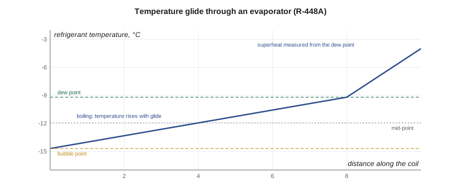
Many modern refrigerants are blends of two or more components. Some blends, such as R-410A, behave almost like a single substance and are called near-azeotropic; their bubble and dew temperatures at a given pressure are within a few tenths of a degree. Others, such as R-407C, R-448A and R-449A, are zeotropic: at a given pressure, the blend starts to boil at its bubble point and finishes at a higher dew point. The difference is called temperature glide, often a few kelvin for these refrigerants. Glide changes how the refrigerant is charged and how readings are interpreted.
- Liquid charging. When vapour is drawn from a cylinder of a zeotropic blend, the more volatile components leave first, so the vapour does not have the blend's composition, and the liquid left behind shifts too. Blends with significant glide must therefore be removed from the cylinder as liquid. Cylinders without dip tubes are inverted; many cylinders have a dip tube and a liquid valve marked for this purpose.
- Charging liquid into a running system. If the system is running and more refrigerant is needed on the low side, liquid must be metered slowly into the suction line so it vaporizes before reaching the compressor, using a charging restrictor or by throttling the manifold valve. Liquid must never be dumped into the suction of a running compressor.
- Reading pressures. A blend's pressure-temperature chart has two columns. Superheat is calculated from the dew point at the suction pressure, because the vapour leaving the evaporator has finished boiling. Subcooling is calculated from the bubble point at the liquid pressure, because the liquid leaving the condenser has just finished condensing.
- Evaporator and condenser temperatures. Because the refrigerant's temperature changes as it boils, the evaporator inlet is colder than the dew point. Some manufacturers and coil selections use a mid-point or mean temperature, halfway between bubble and dew, to describe the evaporator or condenser temperature. Know which one a specification uses.
- Leaks. A blend that leaks as vapour can change composition, but for most current blends the effect of a single leak on performance is small, and manufacturers generally allow topping up after a leak repair. If a system has leaked repeatedly or its performance no longer matches its charge, recover the charge and weigh in new refrigerant.
# Superheat and subcooling for R-448A using the right column (approximate P-T values)
import math
def interp(p, table):
    for (p1, t1), (p2, t2) in zip(table, table[1:]):
        if p1 <= p <= p2:
            f = (math.log(p) - math.log(p1)) / (math.log(p2) - math.log(p1))
            return t1 + f * (t2 - t1)
    raise ValueError("outside table")

# pressure in kPa gauge -> temperature in C (approximate values for R-448A)
dew = [(150, -13.9), (200, -9.2), (250, -5.0), (300, -1.2)]
bubble = [(1300, 32.1), (1500, 36.6), (1700, 40.8), (1900, 44.6)]
bubble_low = [(150, -19.4), (200, -14.7), (250, -10.5), (300, -6.7)]

suction, suction_line = 200, -4.0      # kPa gauge, C at the evaporator outlet
liquid, liquid_line = 1500, 32.0       # kPa gauge, C at the condenser outlet

t_dew = interp(suction, dew)
t_bub_suction = interp(suction, bubble_low)
t_bub_liquid = interp(liquid, bubble)
print(f"evaporator: bubble {t_bub_suction:.1f} C, dew {t_dew:.1f} C, glide {t_dew - t_bub_suction:.1f} K, mid-point {(t_dew + t_bub_suction)/2:.1f} C")
print(f"superheat (from dew):  {suction_line - t_dew:4.1f} K")
print(f"wrong superheat (from bubble): {suction_line - t_bub_suction:4.1f} K  <- overstates it by the glide")
print(f"subcooling (from bubble): {t_bub_liquid - liquid_line:4.1f} K")evaporator: bubble -14.7 C, dew -9.2 C, glide 5.5 K, mid-point -11.9 C superheat (from dew): 5.2 K wrong superheat (from bubble): 10.7 K <- overstates it by the glide subcooling (from bubble): 4.6 K
Using the bubble column for superheat makes the superheat look larger by the full glide, about 6 K (10 °F) in this example. A technician who made that mistake on a TXV system might close the valve, starving the coil; on a fixed-orifice system, they might add refrigerant to bring a correct superheat down, overcharging it. Digital gauges handle this automatically if they are set to the right refrigerant, but the technician still needs to know which value the gauge is showing.
Charging in low ambient conditions
Most manufacturers' superheat and subcooling methods are valid only within a range of outdoor temperatures, because low head pressure changes how the metering device and condenser behave. Below that range, the readings no longer reflect the charge.
- Fixed-orifice systems in cool weather run starved, with high superheat, because the low head pressure pushes less refrigerant through the piston. Adding refrigerant to reach a normal superheat overcharges the system for summer. Manufacturers typically say to weigh in the charge in cool weather, or to return in warm weather to check it.
- Air conditioners with TXVs may be checked by subcooling only above a stated outdoor temperature. Some manufacturers allow a method that restricts condenser airflow, by partly covering the coil, to raise the head pressure into the normal range during the check; follow the instructions exactly if this is permitted.
- Heat pumps can often be checked in heating mode using the manufacturer's heating charging chart, with indoor return air temperature and outdoor temperature as inputs.
- Refrigeration systems with head pressure control, such as the brewery walk-in, are designed to run in cold weather. The head pressure control valve floods the condenser with liquid to hold the head pressure up, so a large part of the charge sits in the condenser in winter, and the receiver level is lower than in summer. Such systems need enough charge for winter flooding; the manufacturer's instructions give how to calculate the extra charge, and the receiver must be large enough to hold it in summer.
For the brewery's walk-in, the charging section in the condensing unit's manual explained exactly this: in winter, check that the sight glass is clear at full load with the head pressure control valve holding its set pressure, and that the receiver level is at least the minimum mark; in summer, the receiver should not be overfilled. Charging to a summer subcooling target in winter would undercharge the system for the next cold snap, when the condenser floods and the receiver runs dry.
Inverter-driven systems
Inverter systems change compressor speed continuously to match the load, and their EEVs, outdoor fans and indoor fans move with them. At any moment, the pressures, superheat and subcooling depend on what the controller has chosen to do, so a technician who reads gauges during normal operation sees a moving target. Manufacturers deal with this in several ways:
- Charge by weight only. Most ductless and many ducted inverter systems are charged by weighing in the nameplate charge plus the line set adjustment from the installation manual, with no field adjustment by superheat or subcooling.
- Test or service mode. Many systems have a mode, selected from a remote control, a button on the outdoor board or a service tool, that runs the compressor and fans at fixed speeds and holds the EEV at a set behaviour, so pressures and temperatures can be compared with the manufacturer's charts.
- Built-in charge checks. Some systems calculate and display a refrigerant level or a charge check result from their own sensors, or flag a low charge from discharge temperature and EEV position.
- Pump-down and recovery functions. Some ductless systems have a pump-down mode that moves the charge into the outdoor unit for service; follow the manufacturer's steps, because closing service valves at the wrong time can damage the compressor.
The result is a simple rule: on inverter systems, the manual is the method. If the manufacturer says to weigh in, do not try to adjust the charge by superheat or subcooling readings taken at variable speed. If it provides a test mode and charts, use them under the stated conditions.
| Situation | Usual method | Watch for |
|---|---|---|
| Zeotropic blend, any system | Liquid from cylinder; meter slowly into suction if running | Dew point for superheat, bubble point for subcooling |
| Fixed orifice, cool weather | Weigh in; check in warm weather | High superheat from low head pressure, not low charge |
| TXV air conditioner, cool weather | Weigh in, or the manufacturer's low-ambient method | Subcooling method limits |
| Refrigeration with head pressure control | Weight plus winter flooding charge; sight glass and receiver level | Not charging to summer targets in winter |
| Inverter or ductless | Weigh in; test mode and charts if provided | Readings that change with speed |
Topping up the walk-in
The brewery's system had lost about a quarter of its 4.5 kg (10 lb) charge before the leak was found. Theo set the R-448A cylinder upright on the scale, confirmed it had a dip tube and a liquid valve, and connected the liquid valve through a charging restrictor to the suction service port. With the system running and the head pressure control valve holding the condensing pressure up despite the cold, he metered liquid in slowly, watching the suction pressure and listening at the compressor, until the sight glass ran clear at full load and the receiver level reached the manual's minimum winter mark. The scale showed 1.1 kg (2.4 lb) added. He calculated the superheat at the coil from the dew point at the suction pressure and recorded both the charge added and the conditions. In the record, he noted that the receiver level should be checked again in summer.
Heat pumps in heating mode
Many manufacturers provide a heating-mode charging chart for heat pumps, because a heat pump that needs service in winter cannot be checked by its cooling targets. In heating, the indoor coil is the condenser and the outdoor coil the evaporator. The chart typically uses the indoor return air temperature and the outdoor air temperature, and gives a target liquid pressure, a target subcooling at the indoor coil or a target discharge pressure, depending on the design. Measurements are taken with the outdoor coil free of frost, so the check is made between defrost cycles, and the system must run long enough after a defrost to settle. Where no heating chart is available, the instructions usually say to weigh in the charge and return in cooling season to verify it. Readings taken during or just after defrost, when the reversing valve has changed position and the coils have changed roles, mean nothing for the charge and should never be used to add refrigerant.
Common mistakes
MistakeCharging a zeotropic blend as vapour from the cylinder.
InsteadRemove blends with glide as liquid, and meter liquid slowly into a running system's suction.
MistakeCalculating superheat from the bubble point.
InsteadUse the dew point for superheat and the bubble point for subcooling.
MistakeCharging a fixed-orifice system to a normal superheat in cool weather.
InsteadWeigh in, or return in warm weather; low head pressure gives high superheat.
MistakeCharging a head-pressure-controlled system to summer targets in winter.
InsteadAllow for winter condenser flooding as the manufacturer describes.
MistakeAdjusting an inverter system's charge by readings at variable speed.
InsteadWeigh in and use the manufacturer's test mode and charts.
Summary and key terms
- Zeotropic blends have glide: they boil from bubble point to dew point at constant pressure.
- Blends with glide are removed from the cylinder as liquid and metered slowly into a running system.
- Superheat uses the dew point; subcooling uses the bubble point; some specifications use the mid-point.
- Below the manufacturer's outdoor temperature limit, superheat and subcooling no longer show the charge reliably.
- Head pressure control floods the condenser in winter; the charge must allow for it.
- Inverter systems are charged by weight and checked only by the manufacturer's test methods.
- Zeotropic blend
- A refrigerant blend whose boiling temperature changes as it boils at constant pressure.
- Near-azeotropic blend
- A blend with very small glide that behaves almost like a single refrigerant.
- Temperature glide
- The difference between the dew and bubble temperatures of a blend at one pressure.
- Mid-point temperature
- The temperature halfway between the bubble and dew points.
- Charging restrictor
- A device that meters liquid refrigerant slowly into a suction line so it vaporizes.
- Condenser flooding
- Head pressure control that backs liquid into the condenser to hold head pressure in cold weather.
- Test mode
- A manufacturer service mode that runs an inverter system at fixed speeds for checks.
Practice problems
Work each problem on paper first, then reveal the answer to check.
R-448A suction is 200 kPa gauge (dew −9.2 °C, bubble −14.7 °C) and the suction line is −4 °C. What is the superheat?
Show answer
5.2 K, calculated from the dew point, not 10.7 K from the bubble point.
A piston system shows 18 K superheat at 12 °C outdoors. Should you add refrigerant?
Show answer
No; low head pressure causes high superheat in cool weather. Weigh in or check in warm weather.
Why must R-407C be charged as liquid?
Show answer
It has significant glide; vapour from the cylinder would have the wrong composition.
A ductless manual says to charge by weight only. What do you do if you suspect a wrong charge?
Show answer
Recover and weigh in the correct charge, using the manual's test mode for any checks.
Lesson quiz · 5 questions
Score 60% or more to complete this lesson.
Create a free account to save your progress, take quizzes and earn a certificate.