
PWR-420 · Lesson 3 of 12 · 23 min
High-voltage systems and protection
▶ Video coming soon A video version of this lesson is on the way.
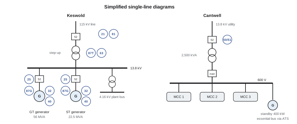
Cantwell takes its power from the utility at 13.8 kV, steps it down to 600 V in one 2,500 kVA transformer, and spends most of its electrical attention on motors, MCCs and the standby generator (PWR-240). Keswold Energy Centre, across the city, is a different world: two generators at 13.8 kV, a step-up transformer to the 115 kV transmission system, and a protection scheme that decides in a few cycles whether a fault inside the plant, or out on the grid, trips a 45 MW gas turbine. Grazyna arranged for Pilar to borrow Keswold's protection one-line diagram and setting summary from Anselm Rasmusen, and they spent a session going through both plants' high-voltage systems side by side.
This lesson describes high-voltage equipment in power and process plants, explains how protective relays detect faults and how the standard device numbers describe them, and works through overcurrent coordination, differential protection and generator protection. It then covers the safety side: switching, access to high-voltage equipment, arc flash and the standards that govern work on electrical systems in each country.
What counts as high voltage
Terms vary between codes and industries. In plant practice, low voltage usually means up to 750 V in Canada (the Canadian Electrical Code's definition) and medium or high voltage means anything above it: the 4.16 kV and 13.8 kV of large motors and plant distribution, and the 115 kV and above of the transmission system. The equipment, the training and the work rules change at that boundary, and so does the energy available in a fault.
High-voltage plant equipment includes switchgear (metal-clad assemblies of circuit breakers, instrument transformers and relays), power transformers with their cooling, oil and gas monitoring, generators and their excitation, large motors for boiler fans, feed pumps and compressors, and the cables, bus ducts and surge arresters that connect them. Medium-voltage circuit breakers are now mostly vacuum or SF₆ insulated; older plants still have air-magnetic and oil breakers.
Protective relays and device numbers
A protective relay watches currents and voltages through current transformers (CTs) and voltage transformers (VTs), decides whether a fault or abnormal condition exists, and trips the right circuit breaker. Modern relays are microprocessor devices that combine many functions, record fault data and communicate with the DCS, but their functions are still described by the standard device numbers of IEEE C37.2, which appear on every protection drawing:
| Number | Function | Typical use |
|---|---|---|
| 21 | Distance | Transmission line and generator backup |
| 25 | Synchronism check | Generator and tie breakers |
| 27 / 59 | Undervoltage / overvoltage | Buses, motors, generators |
| 32 | Directional power | Generator reverse power (motoring) |
| 40 | Loss of field | Generators |
| 46 | Negative sequence current | Generators and motors (unbalance) |
| 49 | Thermal | Motors and transformers |
| 50 / 51 | Instantaneous / time overcurrent | Feeders, transformers, motors |
| 52 | AC circuit breaker | The breaker itself |
| 63 | Pressure (sudden pressure) | Transformer internal faults |
| 81 | Frequency | Generators, load shedding |
| 86 | Lockout relay | Holds trips until reset by hand |
| 87 | Differential | Generators, transformers, buses, large motors |
Protection is judged by four qualities. It must be sensitive enough to detect every fault it is meant to see, selective so that only the breaker nearest the fault trips, fast enough to limit damage and keep the system stable, and reliable, which includes both dependability (it trips when it should) and security (it does not trip when it should not). Selectivity is achieved by coordination of time and current settings, or by zones that the relay can define precisely.
Overcurrent protection and coordination
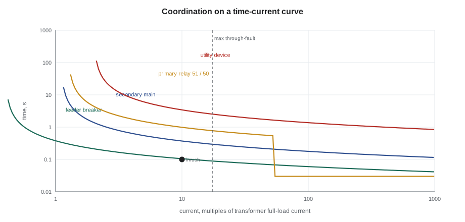
A time overcurrent relay (51) trips after a delay that gets shorter as current rises, following an inverse curve. Its pickup is the current above which it begins to time; its time dial shifts the curve up or down. An instantaneous element (50) trips without intentional delay above a higher setting. Overcurrent devices in series, from a motor starter's overload up through the MCC breaker, the main breaker and the utility's relay or fuse, are coordinated so that each one trips before the device upstream of it for any fault in its own zone. On a time-current curve (TCC) drawing, coordination shows as curves that do not cross, with a margin, often 0.2 to 0.4 seconds for relays, between them.
Worked problem
Setting a transformer primary relay
Cantwell's 2,500 kVA transformer is fed at 13.8 kV and has an impedance of 5.75 in 100; its secondary is 600 V. The primary relay's time overcurrent element is to pick up at 125 in 100 of full-load current, using 150:5 CTs, and the instantaneous element must not trip for a fault on the 600 V side. Find the full-load current, the pickup in primary and secondary amperes, and the minimum instantaneous setting at 125 in 100 of the maximum through-fault current.
Show solution
- \[I_{FL} = \frac{2{,}500}{\sqrt{3} \times 13.8} = 104.6 \text{ A}\]
- \[I_{pickup} = 1.25 \times 104.6 = 130.7 \text{ A primary} = \frac{130.7}{30} = 4.36 \text{ A secondary}\]
- The secondary fault current, limited by the transformer impedance (assuming a strong utility source):
- \[I_{sc,600} = \frac{2{,}406}{0.0575} \approx 41{,}800 \text{ A}, \quad \text{seen on the primary as } 41{,}800 \times \frac{0.6}{13.8} \approx 1{,}819 \text{ A}\]
- \[I_{50} \geq 1.25 \times 1{,}819 \approx 2{,}270 \text{ A primary}\]
Answer: The 150:5 CTs have a ratio of 30, so the relay sees 4.36 A at pickup. The instantaneous element, set above about 2,270 A, trips at once for a fault in the transformer or its primary cable, where the current from the 13.8 kV system is far higher, but leaves faults on the 600 V side to the main breaker. This is the same 42 kA figure that set the interrupting rating of Cantwell's 600 V gear and fed the arc flash study (PWR-240). Transformer inrush, typically 8 to 12 times full-load current for about 0.1 s, must also lie below the relay's curve.
Differential protection
Differential protection (87) compares the current entering a zone with the current leaving it. In normal operation and for faults outside the zone they are equal; a difference means current is going somewhere inside, to a fault. Because it responds only to faults in its own zone, a differential relay can be both very sensitive and very fast without any coordination delay, which makes it the main protection for generators, large transformers, buses and large motors. Percentage restraint allows for CT errors on heavy through-faults: the relay trips only when the difference exceeds a set fraction, the slope, of the current flowing through.
Transformer differential relays must also allow for the different currents on each side, the phase shift of delta-wye connections and the magnetizing inrush on energization, which they recognize by its high second-harmonic content. They are usually backed by a sudden pressure relay (63) and by gas accumulation and oil temperature monitoring, which detect slowly developing internal faults that the differential might not see.
Worked problem
Is it inside the zone?
Keswold's steam turbine generator is rated 22.5 MVA at 13.8 kV. During a load test its neutral-side CTs read 941 A and its terminal-side CTs 930 A (both referred to primary). The differential relay's minimum pickup is set at 0.3 A secondary on 1,200:5 CTs, with a 10 in 100 slope. Should it trip?
Show solution
- \[I_{rated} = \frac{22.5 \times 10^6}{\sqrt{3} \times 13{,}800} = 941 \text{ A}\]
- \[I_{diff} = 941 - 930 = 11 \text{ A primary} = \frac{11}{240} = 0.046 \text{ A secondary}\]
- The difference is about 1.2 in 100 of the through current.
Answer: The difference is about 0.05 A secondary, well under the 0.3 A minimum pickup, and only about 1.2 in 100 of the through current against a 10 in 100 slope. It is CT error and metering mismatch, not a fault, and the relay rightly stays quiet. A stator winding fault would produce a difference of hundreds or thousands of amperes.
Generator protection
A generator needs protection against faults in its own windings and against abnormal conditions imposed by the system or its prime mover. The main functions are:
- Stator differential (87G) for phase faults in the winding.
- Stator ground fault protection (64G or 59N), because most generators are grounded through a high resistance that limits ground fault current to a few amperes, too little for the differential to see.
- Loss of field (40): a generator that loses excitation draws reactive power from the system and overheats its rotor; the relay detects the change in apparent impedance.
- Reverse power (32): if the turbine loses steam or fuel, the generator motors the turbine, which can overheat a steam turbine's last stages; the relay trips after a short delay.
- Negative sequence (46): unbalanced loads or an open phase induce currents in the rotor surface that heat it rapidly.
- Over and under frequency (81), overexcitation (volts per hertz, 24) and over and undervoltage (59 and 27).
- Backup protection for system faults that are not cleared, such as voltage-restrained overcurrent (51V) or distance (21).
The synchronism check relay (25) supervises the generator breaker so that it can close only when voltage, frequency and phase angle are within limits, which protects against the damaging torque of an out-of-phase closure (PWR-320). Most generator trips act through a lockout relay (86), which trips the breaker, the field and often the prime mover, and must be reset by hand, so that nobody recloses on a fault without investigating.
At Keswold, reverse power on the steam turbine generator trips after about 10 seconds, long enough to ride through a brief swing but short enough to protect the last stage blades. Liesl Brannagan told Pilar that in six years the 87G had never operated, but the 32 had twice, both times when the extraction control was being tuned after an outage. "It is the relays for abnormal conditions that work for a living," she said. "The fault relays sit and wait, like the SIS."
Switching and access to high-voltage equipment
Switching high-voltage equipment is a planned activity. Most large plants require a written switching order listing each step in sequence, prepared and checked by a qualified person and carried out by a qualified operator, often with a second person reading each step. Isolation for work means opening and racking out or locking open the breaker, opening and locking the disconnect, testing for absence of voltage with a rated detector proved before and after, and applying temporary protective grounds where the work requires them. The equipment is then released for work under a work permit or high-voltage access permit that names the limits of the safe zone.
In Ontario, the Occupational Health and Safety Act and the regulation for industrial establishments set the general duties for electrical work, the Ontario Electrical Safety Code governs installations, and CSA Z462 gives the detailed method for workplace electrical safety. Utilities and their contractors follow the utility work protection code their employer adopts. Keswold's interface with the transmission system is also governed by the transmitter's and the IESO's operating requirements, so switching at the 115 kV breaker is coordinated with the transmitter's control centre.
Arc flash
An arc flash is the release of energy when current flows through air between conductors or to ground. It produces intense heat, a pressure wave, molten metal and noise, and it can kill or burn a worker standing several metres away. The hazard is assessed by an arc flash risk assessment, usually a study that calculates the incident energy at a working distance for each piece of equipment, expressed in cal/cm², and the arc flash boundary at which a bare-skin second-degree burn could occur.
The governing standard in Canada is CSA Z462, *Workplace electrical safety*, whose 2024 edition (CSA Z462:24) is harmonized closely with NFPA 70E-2024 in the US. Both require the employer to have an electrical safety program, to establish an electrically safe work condition as the first choice, and to justify any work on energized equipment. Cantwell's 2025 study put MCC 3 at 6.8 cal/cm² (about 28 J/cm²) at a working distance of 455 mm, with an arc flash boundary of 1.4 m (PWR-240), and the label on the door states the PPE needed for the few tasks, such as testing for absence of voltage, that have to be done before the equipment is proven dead.
Protection settings and arc flash are linked. Incident energy is roughly proportional to the arc current multiplied by the time it flows, so the clearing time of the upstream protective device matters as much as the fault level. Plants reduce arc flash energy with faster protection: maintenance switches that temporarily enable an instantaneous trip, zone-selective interlocking, arc-sensing relays that detect light and current together, and remote racking and switching so that the operator is outside the boundary. Any change in relay settings or in the utility's fault level changes the study, so the study must be reviewed whenever the system changes and at least every five years.
"At Keswold they won't rack a 13.8 kV breaker by hand any more," Pilar told Grazyna afterwards. "They use a remote racking motor and stand in the next room. When I asked why, Liesl just said: because the study told us to."
Common mistakes
MistakeSetting an instantaneous element below the through-fault current of a downstream fault.
InsteadSet it above the maximum through-fault current with a margin, so the downstream device clears its own faults.
MistakeExpecting the generator differential to catch stator ground faults on a high-resistance grounded machine.
InsteadUse dedicated stator ground fault protection.
MistakeResetting a lockout relay to restore power quickly.
InsteadFind and clear the cause first; the 86 exists to force that.
MistakeTesting for absence of voltage without proving the detector.
InsteadProve the detector on a known source before and after the test.
MistakeTreating an arc flash label as permanent.
InsteadReview the study when settings, equipment or the utility fault level change, and at least every five years.
MistakeClosing a generator breaker without synchronism supervision.
InsteadUse a 25 relay or synchronizer to check voltage, frequency and phase angle.
Summary and key terms
- Plant high-voltage equipment includes switchgear, transformers, generators, large motors and cables; work rules and fault energy change above low voltage.
- Protective relays detect faults through CTs and VTs and are described by IEEE C37.2 device numbers; protection must be sensitive, selective, fast and reliable.
- Time and instantaneous overcurrent elements are coordinated on time-current curves; instantaneous settings must clear downstream through-faults.
- Differential protection compares current in and out of a zone; transformers add inrush restraint and sudden pressure relays.
- Generators need differential, stator ground, loss of field, reverse power, negative sequence, frequency and backup protection, with synchronism check and lockout relays.
- Switching follows written orders, isolation, testing for absence of voltage and grounding; arc flash is assessed by study under CSA Z462 or NFPA 70E and reduced by faster protection.
- Protective relay
- A device that detects faults or abnormal conditions and trips circuit breakers.
- Device number
- The IEEE C37.2 number that identifies a protective function, such as 51 or 87.
- Pickup
- The current or other quantity at which a relay begins to operate.
- Coordination
- Setting protective devices so that the one nearest a fault trips first.
- Differential protection
- Protection that trips on a difference between current entering and leaving a zone.
- Lockout relay
- A relay that holds a trip until it is reset by hand.
- Synchronism check
- Supervision that allows a breaker to close only when the two sides are in step.
- Incident energy
- The heat energy at a working distance from an arc, in cal/cm².
- Arc flash boundary
- The distance at which an arc could cause a second-degree burn to bare skin.
Practice problems
Work each problem on paper first, then reveal the answer to check.
Full-load current of a 1,500 kVA transformer at 4.16 kV?
Show answer
About 208 A.
Which device number is a lockout relay?
Show answer
86.
A 51 relay on 200:5 CTs has a primary pickup of 260 A. Secondary pickup?
Show answer
6.5 A.
Why does a generator need a 32 relay?
Show answer
To trip on reverse power, when the generator motors its turbine.
Lesson quiz · 5 questions
Score 60% or more to complete this lesson.
Create a free account to save your progress, take quizzes and earn a certificate.