
PWR-420 · Lesson 1 of 12 · 28 min
Advanced process control and DCS
▶ Video coming soon A video version of this lesson is on the way.
Pilar Quenneville had been a shift engineer at Cantwell Energy Centre for nine years when she enrolled, in the autumn of 2026, in a part-time Second Class Power Engineering course. She held a Third Class certificate, which is what Cantwell's registration requires of a shift engineer in a plant whose chief must hold a Second Class certificate, and her years as a third-class operating engineer in that plant already counted toward the experience TSSA asks of a Second Class candidate. Grazyna Wolanski, the chief engineer, had offered to meet her once a week through the course, usually in the quiet hour after the day shift's handover.
"The Second Class material changes direction," Grazyna said at their first session. "Up to Third Class you learn how each machine works and how to run it. From here on you learn how the whole plant is controlled, protected, paid for and staffed, because the person who holds this certificate is often the one who decides those things." They started with the system Pilar used every shift and understood least: the distributed control system.
This lesson describes the architecture of a distributed control system, how it differs from a programmable logic controller and from a burner management system, and how its controllers, networks, operator stations, engineering station and historian fit together. It then works through the control strategies beyond a single feedback loop that a Second Class engineer is expected to understand: cascade, feedforward, ratio, split range, override and selector control, and an introduction to model predictive control. It finishes with loop performance and the discipline of managing changes to a control system.
What a DCS is
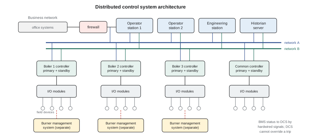
A distributed control system (DCS) spreads control across several controllers, each responsible for part of the plant, linked by a control network to operator stations in the control room and to an engineering station where the configuration is built and changed. The word distributed refers to that division: a fault in one controller affects only the equipment it controls, unlike the central computer systems of the 1960s, where one failure could stop everything.
A DCS is built for continuous process control. It handles hundreds or thousands of analogue loops, keeps a single plant-wide database of tags, alarms and trends, and is configured with function blocks for measurement, control and logic. A programmable logic controller (PLC) grew up in discrete manufacturing and excels at fast sequential and interlock logic; modern PLCs can run process loops too, and the boundary has blurred, but many plants still use PLCs for packaged equipment such as water treatment skids, compressors and chillers, connected to the DCS through a communication link.
The parts of the system
- Controllers execute the control strategy, typically every 100 ms to 1 s for process loops. Critical controllers are often redundant: a primary and a hot standby that takes over without a bump if the primary fails.
- Input and output (I/O) modules convert field signals to data: analogue inputs (4–20 mA, often with HART digital data superimposed), analogue outputs to valve positioners and drives, discrete inputs from switches and contacts, and discrete outputs to starters and solenoids. Newer plants also use fieldbus networks or Ethernet-based field protocols that carry many devices on one cable.
- The control network links controllers, stations and servers. It is usually duplicated (two independent networks, A and B) so that a cable or switch failure does not blind the operators.
- Operator stations (the human-machine interface, HMI) display graphics, alarms and trends and let the operator change set points, modes and outputs.
- The engineering station holds the configuration database. Changes to control logic, tuning and alarms are made here, downloaded to controllers and recorded.
- The historian stores process values, alarms and operator actions, often for years, and supplies data to reports, performance calculations and investigations.
At Cantwell, each of the three steam boilers has its own controller, and a fourth, common controller handles the deaerator, feed pumps, header pressure, district loop and auxiliaries. The network is redundant, the operator stations and controllers run from the plant's uninterruptible power supply, and the historian keeps two years of one-second data. Sallow Creek Controls supports the system under a service contract, and when Wendeline Achterberg needs remote access, the session is opened from the plant end and closed when she finishes (PWR-240).
Keeping safety functions separate
The DCS is the basic process control system (BPCS): it keeps the plant at its set points. The functions that protect people and equipment when control fails belong in separate systems. Each Cantwell boiler has its own burner management system (BMS), which runs the purge, ignition and flame supervision sequence and trips the fuel on unsafe conditions. The DCS can request a start or read the BMS status, but it cannot override a BMS trip. Lesson 2 explains why that independence matters and how safety instrumented systems are designed.
Cyber security belongs to the same discussion. A DCS that is connected to a business network or to the internet can be attacked. Good practice places the control network behind a firewall in its own zone, allows only the connections that are needed, controls remote access, keeps backups of configurations, and manages software patches through a tested process. The IEC 62443 series sets out a framework for industrial control system security that many plants and suppliers now follow.
Beyond the single loop
Pilar knew the single feedback loop well: a transmitter measures a variable, the controller compares it with the set point, and the output moves a valve to reduce the error, with proportional, integral and derivative action tuned to the process (PWR-240). A single loop works well when the process responds quickly and disturbances are small. Many plant variables do not behave that way, and the strategies below were developed to handle them.
Cascade control
In cascade control, the output of one controller, the primary or outer controller, becomes the set point of another, the secondary or inner controller. The inner loop controls a faster variable that responds directly to the final element and catches disturbances before they reach the outer variable. A familiar example is a heater outlet temperature controller whose output sets the set point of a fuel flow controller: if the fuel supply pressure rises, the flow controller corrects the fuel flow within seconds, long before the outlet temperature would have moved.
For cascade to work, the inner loop must be considerably faster than the outer loop, a common rule of thumb being three to five times faster or more. The inner loop is tuned first, in automatic, then the outer loop is tuned with the inner loop in cascade. If the inner loop is put in manual or its transmitter fails, the outer loop must stop acting, or its integral action will wind up.
Worked problem
Is the cascade fast enough?
A deaerator level controller (outer loop) has an effective response time of about 4 minutes. Its output sets the set point of a makeup water flow controller (inner loop), which settles in about 20 seconds after a set point change. Is the speed ratio adequate?
Show solution
- \[\frac{240 \text{ s}}{20 \text{ s}} = 12\]
Answer: The inner loop is about twelve times faster than the outer loop, well above the minimum of three to five, so the cascade is sound. A flow loop under a level loop is the classic cascade pair, because flow responds in seconds and level in minutes.
Feedforward control
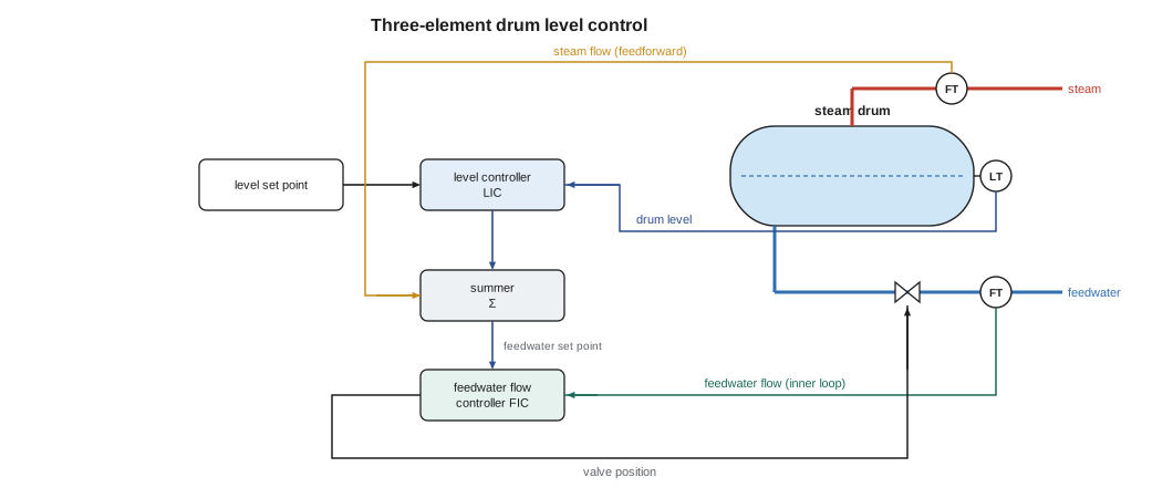
Feedback control waits for an error before it acts. Feedforward control measures a disturbance and acts before the controlled variable moves, using a model of how the disturbance affects the process. Feedforward is almost never used alone, because no model is perfect, so it is combined with feedback: feedforward does most of the work quickly, and feedback trims the remaining error.
The best known example in a boiler plant is three-element drum level control. A single-element controller uses only drum level, and it reacts badly to a sudden load increase: the drum level rises at first because of swell, so a level-only controller cuts feedwater just when more is needed. The three-element strategy adds steam flow as a feedforward signal and feedwater flow as the inner loop of a cascade. The level controller's output is added to the steam flow signal to form the feedwater flow set point, so that feedwater follows steam flow immediately and the level controller only corrects the slow mismatch.
Worked problem
Feedforward on a load step
Boiler 2 is steaming at 6,000 kg/h when a cold morning raises its demand to 9,000 kg/h within two minutes. Continuous blowdown takes about 3 in 100 of the steam flow, so the plant's feedforward gain is set at 1.03. How much does the feedforward path raise the feedwater set point, before the level controller does anything?
Show solution
- \[\Delta \dot m_{fw} = 1.03 \times (9{,}000 - 6{,}000) = 3{,}090 \text{ kg/h}\]
Answer: The feedwater set point rises by about 3,090 kg/h as fast as the steam flow transmitter sees the change. The level controller's job is reduced to trimming the small error left by swell, blowdown variations and transmitter error. Without the feedforward path, the level controller would first cut feedwater on the swell and then have to recover a 3,000 kg/h mismatch from a falling level.
Grazyna reminded Pilar of October 16, when boiler 3 ran on single-element control while its steam flow transmitter was calibrated (PWR-220). "That morning the shift had to keep boiler 3 off the swing duty and watch it by hand. A three-element system with one element missing is a single-element system, and it needs a different operating plan."
Ratio control
Ratio control keeps one flow in a set proportion to another, the wild flow, which is set elsewhere. The controlled flow's set point is the wild flow multiplied by the ratio. Chemical feed proportioned to makeup water flow is a simple example. The most important ratio in a boiler is air to fuel.
A pure ratio scheme would let the air lag behind the fuel on a load increase, creating a fuel-rich, dangerous mixture for a few seconds. Fuel-air control therefore uses cross-limiting (also called lead-lag): on a load increase, air leads and fuel follows, because the fuel demand is limited to what the measured air flow can burn; on a load decrease, fuel leads and air follows, because the air demand cannot fall below what the measured fuel flow needs. Cantwell's burners use parallel positioning, with fuel and air dampers driven together on characterized curves, and boiler 1 adds oxygen trim (PWR-220), but the full metering cross-limited scheme is common on larger boilers, including Keswold's duct burners.
Worked problem
An air flow set point from the ratio
At full fire a Cantwell boiler burns about 940 m³/h of natural gas. The gas needs about 9.61 m³ of air per m³ for complete combustion (PWR-330), and the boiler is run at about 10 in 100 excess air at high fire. What air flow should the ratio controller ask for?
Show solution
- \[\dot V_{air} = 940 \times 9.61 \times 1.10 \approx 9{,}930 \text{ m}^3/\text{h} \approx 166 \text{ m}^3/\text{min}\]
Answer: The ratio is the stoichiometric air requirement multiplied by one plus the excess air fraction. In practice the ratio is not fixed: it is characterized against load, because burners need more excess air at low fire, and an oxygen trim controller adjusts it slowly to hold the measured flue gas oxygen at its set point.
Split range, override and selector control
Split range control uses one controller output to operate two or more final elements in sequence. A pressure controller might open a makeup valve over the first half of its output and a vent valve over the second, or a temperature controller might drive a heating valve over 0 to 50 in 100 of output and a cooling valve from 50 to 100. The ranges must be arranged so that both elements are never open against each other, unless a small overlap is intended.
Override control lets a second controller take over the final element when a constraint is approached. The two controller outputs go to a low selector or high selector, which passes the lower or higher of the two. For example, a feed pump discharge flow controller can be overridden by a suction pressure controller that reduces the pump's speed if suction pressure approaches the cavitation point, which is the kind of protection the deaerator review discussed after the October 27 cavitation (PWR-340). The controller that is not selected must be protected from reset windup, usually by feeding the selected output back to it.
Selector control can also choose between measurements: a high selector on several furnace temperature thermocouples protects against the hottest one, while a median selector on three redundant transmitters rejects a single failed reading. Cantwell's header pressure controller sends one demand to the three boiler masters, each with an operator bias, and a selector logic keeps each boiler's demand within its own firing limits.
Model predictive control
Model predictive control (MPC) uses a dynamic model of the process, built from step tests, to predict how several controlled variables will respond to moves in several manipulated variables over the next minutes or hours. Every control interval it calculates the best sequence of moves that keeps the controlled variables near their targets without violating constraints such as valve limits, temperature limits and emissions, implements the first move, and repeats the calculation with fresh measurements. MPC usually sits above the DCS, writing set points to its regulatory loops.
MPC pays off where variables interact strongly and the plant runs against constraints, as in a refinery unit, a large utility boiler optimizing steam temperatures and NOx, or a combined cycle plant balancing duct firing, export power and steam to a host. Keswold uses an optimization package that sets duct burner firing and extraction flow to meet Marrowby's steam demand at the lowest fuel cost; a plant the size of Cantwell gains little from it. Whatever the scale, MPC depends on well-tuned regulatory loops beneath it: an advanced controller writing set points to oscillating loops makes things worse.
Loop performance and tuning
A Second Class engineer should be able to judge whether a loop is performing. The first questions are practical: is the loop in automatic? Operators put loops in manual when they do not trust them, and a historian report of the time each loop spends in manual is often the most revealing performance measure a plant can produce. Other measures include the variability of the controlled variable, the travel and reversals of the valve, and the settling time after a set point change or disturbance.
Poor performance usually has a mechanical cause before a tuning cause. A sticky valve with stiction produces a slow limit cycle that no tuning can cure; a valve that is too large spends its life nearly closed with poor resolution; a transmitter with too much damping hides the process from the controller. The order of work is: check the measurement, check the final element, then tune. When tuning is needed, it is done from step tests with a recognized method, recorded, and treated as a change.
Wendeline's retuning of the hot water supply temperature loop on October 2 followed exactly that order (PWR-240). She checked the transmitter and the valve stroke, found the gain too high for the loop's new dead time, reduced it from 2.5 to 1.2 and lengthened the integral time from 2 to 4 minutes, and the change went through management of change with the before and after trends attached.
Managing the control system
A DCS configuration is a safety-related engineering document, and changes to it, from a new alarm limit to a rewritten sequence, need the same discipline as changes to equipment: a request, a review, approval, testing, documentation and a record of who downloaded what and when. Most plants also restrict who can change what: operators can change set points and modes within limits, but only authorized engineers or technicians can change tuning, alarms or logic. A current backup of the configuration, stored off the system, is the plant's protection against a failed server, a corrupted download or a cyber incident.
"The best control system in the world can't run a plant whose operators don't trust it," Grazyna said. "If a loop is in manual on every shift, find out why. It will be a sticky valve, a bad transmitter or a tuning nobody understands, and each of those is fixable."
Common mistakes
MistakeTuning the outer loop of a cascade before the inner loop.
InsteadTune the inner loop first, then the outer loop with the inner in cascade.
MistakeRelying on feedforward alone.
InsteadCombine feedforward with feedback to trim model errors.
MistakeLetting fuel lead air on a load increase.
InsteadUse cross-limiting: air leads on increase, fuel leads on decrease.
MistakeRetuning a loop that oscillates because of a sticky valve.
InsteadCheck the measurement and final element before tuning.
MistakeLetting the DCS override a burner management trip.
InsteadKeep protective functions in an independent system.
MistakeIgnoring reset windup in override schemes.
InsteadFeed the selected output back to the unselected controller.
Summary and key terms
- A DCS distributes control across redundant controllers, I/O, a redundant network, operator and engineering stations and a historian; PLCs often run packaged equipment.
- Protective functions such as the BMS are kept separate from the basic process control system.
- Cascade puts a fast inner loop under a slower outer loop; feedforward acts on a measured disturbance; three-element drum level combines both.
- Ratio control holds one flow in proportion to another; fuel-air control uses cross-limiting so that air leads on increase and fuel leads on decrease.
- Split range, override and selector schemes handle multiple final elements and constraints; MPC optimizes several interacting variables above the DCS.
- Loop performance starts with time in automatic, measurements and valves; control system changes need MOC, access control and backups.
- Distributed control system
- A control system with control spread across several networked controllers and shared operator stations.
- Cascade control
- A scheme in which one controller sets the set point of a faster inner controller.
- Feedforward control
- Control action based on a measured disturbance before the controlled variable changes.
- Ratio control
- Control that keeps one flow in a set proportion to another.
- Cross-limiting
- Fuel-air control logic in which air leads fuel on increases and fuel leads air on decreases.
- Override control
- A scheme in which a constraint controller takes over the final element through a selector.
- Reset windup
- Accumulation of integral action in a controller whose output is not being used.
- Stiction
- Static friction in a valve that makes it stick and then jump.
- Model predictive control
- Multivariable control that uses a process model to plan moves within constraints.
Practice problems
Work each problem on paper first, then reveal the answer to check.
An outer loop responds in 6 minutes and the inner loop in 40 seconds. Speed ratio?
Show answer
9; adequate.
Steam flow rises 2,000 kg/h with a feedforward gain of 1.03. Feedwater set point change?
Show answer
2,060 kg/h.
A boiler burns 600 m³/h of gas needing 9.61 m³ air per m³ at 15 in 100 excess air. Air flow?
Show answer
About 6,630 m³/h.
On a load decrease with cross-limiting, which leads?
Show answer
Fuel leads; air follows.
Lesson quiz · 5 questions
Score 60% or more to complete this lesson.
Create a free account to save your progress, take quizzes and earn a certificate.