
PWR-220 · Lesson 5 of 12 · 28 min
Boiler controls and instrumentation
▶ Video coming soon A video version of this lesson is on the way.
At 06:20 on Friday, October 16, 2026, the district steam load at Cantwell began its usual morning climb. Office towers, the seniors' residence and the other customer buildings were bringing their heating up for the day, and in fifteen minutes the plant's steam flow nearly doubled. Lorne Fitzwilliam had Tamar Ellingsen sit at the control screen beside him. "Watch the drum levels when the load comes on," he said. "Boilers 1 and 2 are on three-element control. Boiler 3 is on single-element this morning, because the instrument technician has its steam flow transmitter out for calibration. You are about to see why we prefer three."
This lesson covers the instruments that measure what a boiler is doing and the controls that act on those measurements: control loops, drum level control and the effect of shrink and swell, steam pressure control, low water protection and safety valves. Combustion control and draft, which use the same ideas, are covered in lesson 6.
Measurements
Every control and every operating decision starts with a measurement. The main ones on a boiler are:
- Pressure, by Bourdon tube gauges for local reading and by electronic pressure transmitters that send a signal, typically 4 to 20 milliamps, to the control system.
- Temperature, by thermocouples (two dissimilar metals joined at a tip, producing a small voltage that rises with temperature) and resistance temperature detectors (RTDs, whose resistance rises with temperature). Both are usually fitted in thermowells so they can be removed under pressure.
- Flow, most often by a differential pressure (DP) element such as an orifice plate, flow nozzle or venturi, with a DP transmitter. Steam flow, feedwater flow, fuel flow and air flow are all measured this way or with magnetic, vortex or Coriolis meters.
- Level, by the gauge glass, which is the direct and legally required indication, and by remote level transmitters, usually DP transmitters with a reference leg.
Differential pressure flow meters have one property every operator should know: the DP rises with the square of the flow. Doubling the flow makes the DP four times as large. The transmitter or control system takes the square root to give a reading that is proportional to flow.
Worked problem
Reading a differential pressure flow meter
Boiler 1's steam flow orifice gives 25 kPa of differential pressure at its full-scale flow of 12,000 kg/h. What is the flow when the DP is 6.25 kPa?
Show solution
- \[\text{flow} = 12{,}000 \times \sqrt{6.25 \div 25} = 12{,}000 \times \sqrt{0.25} = 12{,}000 \times 0.5 = 6{,}000 \text{ kg/h}\]
Answer: A quarter of the full DP means half the full flow. This is also why DP flow meters are inaccurate at low flows: at 10 in 100 of full flow the DP is only 1 in 100 of full scale, and a small zero error becomes a large flow error.
Control loops
A control loop has four parts: a measurement of the process variable (such as drum level), a set point (the value wanted), a controller that compares the two and calculates an output, and a final control element (such as the feedwater control valve) that acts on the process. The difference between set point and measurement is the error.
Most boiler controllers use some combination of three actions:
- Proportional action moves the output in proportion to the error. On its own it leaves a steady offset: the level settles a little away from the set point when the load changes.
- Integral or reset action keeps moving the output as long as any error remains, removing the offset. Too much integral action makes the loop overshoot and swing.
- Derivative or rate action responds to how fast the error is changing, helping slow processes respond quickly. It is used sparingly, because noisy signals make it jumpy.
Controllers are also arranged in combinations. In feedforward control a measured disturbance, such as steam flow, moves the output before it has upset the process. In cascade control one controller's output becomes the set point of another, as when a drum level controller sets the feedwater flow controller's set point. Cantwell's boilers use a distributed control system, but the same ideas apply whether the controller is a computer, a stand-alone electronic unit or an old pneumatic instrument.
Every loop has a manual mode in which the operator sets the output directly. Switching between auto and manual should be bumpless, with the output unchanged at the moment of transfer. An operator who puts a loop in manual must watch it until it is back in auto.
Shrink and swell
The water in a steaming drum is not solid water. The risers and drum are full of steam bubbles, and the bubbles take up space. When pressure falls, as it does when steam demand suddenly rises, some of the hot water flashes, more bubbles form, and the existing bubbles grow. The mixture swells and the level rises, even though the boiler is losing water faster than before. When steam demand suddenly falls, pressure rises, bubbles collapse, and the level shrinks, even though the boiler now has more water than it needs.
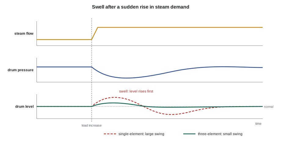
Shrink and swell trick a simple level controller. On a sudden load increase the level rises, so the controller closes the feedwater valve, exactly when the boiler needs more water. When the bubbles settle, the level drops sharply, and the controller has to catch up. In the worst case the level can fall to the low water cutoff just after a load increase, or rise high enough on a sudden load drop to carry water over into the steam line.
Single-, two- and three-element control
Drum level control is described by the number of measurements it uses:
- Single-element control uses drum level alone. It is simple and works for small boilers with steady loads and large water volumes, but it responds the wrong way to shrink and swell.
- Two-element control adds steam flow as a feedforward signal. When steam flow rises, the feedwater valve opens at once, before the level controller has seen any change.
- Three-element control adds feedwater flow. The level controller's output and the steam flow signal together set the feedwater flow set point, and a feedwater flow controller holds the actual feed flow at that set point. In steady operation, feed flow matches steam flow plus blowdown, and the level controller only trims.
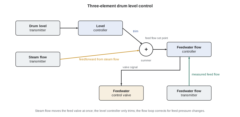
Three-element control also handles changes in feedwater supply pressure. If a second feed pump starts and the feed header pressure rises, the feedwater flow controller sees the extra flow at once and closes the valve slightly; a single-element controller would not know until the level rose.
Lorne pointed to the trends. As the load rose, boiler 1's level rose about 40 mm (1½ in) and settled back within two minutes, while its feed flow climbed smoothly with its steam flow. Boiler 3's level jumped nearly 100 mm (4 in); its feedwater valve closed partly and then opened wide as the level fell back below normal, and the level overshot before settling. "Same boiler design, same load swing," Lorne said. "The difference is that boiler 3's controller is reacting to the swell instead of the steam flow. If the morning load came on any faster, I would put it in manual and lead the feed valve myself." The steam flow transmitter came back from calibration that afternoon, and boiler 3 was returned to three-element control.
Level measurement and its errors
The gauge glass is the primary level indication. A high-pressure boiler must have at least one directly connected gauge glass, and boilers above a certain pressure need two independent level indications, one of which may be a remote indicator. The gauge glass is connected to the drum by top and bottom connections with valves, and a drain valve at the bottom allows it to be blown down to prove the connections are clear.
The water in a gauge glass is cooler than the water in the drum, because the glass and its piping lose heat. Cooler water is denser, so the glass shows a slightly lower level than the true level in the drum. The same effect makes DP level transmitters read wrongly unless their calculation is compensated for drum pressure.
Worked problem
Why the glass reads low
The drum water at 185 °C has a density of about 882 kg/m³ and stands 200 mm above the glass's bottom connection. The water in the glass is at about 150 °C, density about 917 kg/m³. Ignoring the steam above, what level does the glass show?
Show solution
- The two columns balance at the bottom connection, so height × density is the same:
- \[h_{glass} = 200 \times \frac{882}{917} \approx 192 \text{ mm}\]
Answer: The glass reads about 8 mm low. Real drums add further effects from the steam bubbles in the drum water, so the manufacturer sets the normal water line and alarm points to allow for them. The point for operators is that the glass is not a perfect window on the drum, and remote indicators must be checked against it regularly.
Operators blow down the gauge glass and its water column on a set schedule, typically each shift, to clear sediment from the connections. The correct sequence is to close the top valve and open the drain to blow the bottom connection, then close the bottom and open the top to blow the steam side, and finally close the drain and open both valves. The water should return quickly to the same level. A sluggish return means a connection is partly blocked.
Low water protection
A low water fuel cutoff shuts off the burner when the water level falls to a set point above the lowest safe level. High-pressure boilers are typically required to have two independent low water cutoffs, with the second set lower, and the lower one usually needs a manual reset, so the boiler cannot restart until someone has checked why the level fell. The devices may be float types in an external chamber or conductivity probes inserted in the drum or water column.
The cutoffs must be tested on the schedule the jurisdiction, the insurer and the manufacturer require. A blowdown test drains the float chamber or water column and proves the switch operates. An evaporation test, done less often and under supervision, shuts off the feedwater with the boiler firing at low rate and lets the level fall naturally until the cutoff trips. It proves the whole system, including the drum connections. Every test is logged with the time, the level at which it tripped and the name of the person who did it.
A high water alarm and sometimes a high water cutoff protect against carryover. A feed pump control may start and stop pumps on level in smaller boilers, but on boilers like Cantwell's the feed pumps run continuously and the control valve does the work.
Pressure control
The steam pressure controller, often called the master controller, compares header pressure with its set point and sends a firing rate demand to the combustion control of each boiler that is on automatic. When customers draw more steam, header pressure starts to fall; the master raises the firing rate demand, and the boilers fire harder until pressure recovers. When several boilers share a header, a boiler master or load allocator divides the demand between them, and the operator can bias one boiler to carry more or less than its share.
Each boiler also has a high-pressure limit control, a separate pressure switch that shuts off the burner at a set point below the safety valve setting. It needs a manual reset after it trips. It is part of the burner management system, not the combustion control. Its job is to stop the boiler before the safety valves must lift.
Safety valves
The safety valve is the last protection against overpressure. On a power boiler it is a spring-loaded, full-lift pop valve, built and stamped to Section I and sealed after it is set. Several terms describe its behaviour:
- Set pressure or popping pressure: the pressure at which the valve opens.
- Accumulation: the rise in pressure above the set pressure while the valve is relieving. The safety valves together must have enough capacity to discharge all the steam the boiler can make without the pressure rising more than 6 in 100 above the highest set pressure, which itself may not exceed MAWP.
- Blowdown: the difference between the set pressure and the pressure at which the valve closes again, expressed as a fraction of the set pressure. It is adjusted with the blowdown ring (or adjusting ring), which changes the shape of the huddling chamber around the disc. A typical blowdown is a few in 100 of the set pressure.
- Simmer and chatter: leaking before the valve pops, and rapid opening and closing that can damage the seat. Chatter often means the valve is oversized for the flow or the inlet pressure drop is too large.
A boiler with more than about 47 m² (500 ft²) of heating surface, or an output above a certain rate, must have two or more safety valves. Cantwell's steam boilers have two each.
Worked problem
Safety valve accumulation and blowdown
Boiler 1's safety valves are set at 1,380 kPa, its MAWP. What is the highest pressure allowed while they relieve, and at what pressure would a valve with a blowdown of 4 in 100 reseat?
Show solution
- Accumulation limit:
- \[1{,}380 \times 1.06 \approx 1{,}463 \text{ kPa}\]
- Reseat pressure:
- \[1{,}380 \times (1 - 0.04) = 1{,}380 \times 0.96 \approx 1{,}325 \text{ kPa}\]
Answer: The pressure must not exceed about 1,463 kPa while relieving, and the valve would reseat at about 1,325 kPa. Too little blowdown and the valve may chatter or reseat before the cause of the overpressure has cleared; too much and the boiler loses a lot of steam and pressure each time the valve lifts. Only qualified valve repairers adjust blowdown rings and reseal the valve.
Operators test safety valves by raising boiler pressure to the set point (a pop test) or by lifting them with the try lever at pressure, where the jurisdiction and insurer require it; the frequency and the method are set by them and the plant's procedures. Discharge piping must be supported independently and drained, so no load or water rests on the valve body.
Burner management and interlocks
Controls that keep a boiler running well are separate from those that keep it safe. The burner management system (BMS), or flame safeguard, supervises the burner's start-up sequence and shuts it down on unsafe conditions: flame failure, low water, high pressure, low or high fuel pressure, loss of combustion air or failure of the purge. The combustion control system adjusts fuel and air for the load. The two are kept independent so that a fault in the control system cannot defeat a safety trip. Permissives are conditions that must be met before a step can proceed, such as proving the air damper open for the purge; interlocks stop the boiler if a condition is lost.
Bypassing a safety interlock, even briefly to keep a boiler running, removes the protection it gives. Plants treat any bypass as a formal, recorded, time-limited exception, approved by the chief engineer and covered by extra precautions.
Common mistakes
MistakeExpecting the drum level to fall the instant steam demand rises.
InsteadSwell makes it rise first; the controller must lead with steam flow.
MistakeReading a DP flow signal as if it were linear.
InsteadFlow is proportional to the square root of DP.
MistakeTrusting a remote level indicator without checking the gauge glass.
InsteadCompare them every shift; the glass is the primary indication.
MistakeLeaving a loop in manual unattended.
InsteadWatch it until it is back in automatic.
MistakeTreating the high-pressure limit and the safety valve as the same protection.
InsteadThe limit stops firing first; the safety valve is the last resort.
Summary and key terms
- Boiler instruments measure pressure, temperature, flow and level; DP flow meters read the square of the flow.
- A control loop compares a process variable with a set point and moves a final control element, using proportional, integral and derivative action.
- Shrink and swell make drum level move the wrong way after load changes; three-element control uses steam flow and feed flow to correct for it.
- Gauge glasses read slightly low because their water is cooler and denser; they must be blown down and compared with remote indicators.
- Two low water cutoffs, a high-pressure limit and safety valves protect the boiler; all are tested and logged.
- Safety valves must relieve with no more than 6 in 100 accumulation above set pressure; blowdown is adjusted with the blowdown ring.
- Process variable
- The measured quantity a control loop holds at its set point.
- Feedforward
- Control action taken from a measured disturbance before it upsets the process.
- Cascade control
- An arrangement in which one controller sets the set point of another.
- Swell
- A rise in drum level caused by a fall in pressure and growth of steam bubbles.
- Shrink
- A fall in drum level caused by a rise in pressure and collapse of steam bubbles.
- Three-element control
- Drum level control using drum level, steam flow and feedwater flow.
- Accumulation
- The rise in pressure above set pressure while a safety valve relieves.
- Blowdown (safety valve)
- The difference between set pressure and reseating pressure of a safety valve.
Practice problems
Work each problem on paper first, then reveal the answer to check.
A DP flow meter reads 100 in 100 of DP at 8,000 kg/h. What is the flow at 36 in 100 of full DP?
Show answer
4,800 kg/h (8,000 × 0.6).
A safety valve set at 1,200 kPa has a blowdown of 5 in 100. At what pressure does it reseat?
Show answer
1,140 kPa.
What is the accumulation limit for valves set at 1,035 kPa?
Show answer
About 1,097 kPa.
Why does a single-element controller close the feed valve after a sudden load increase?
Show answer
Swell makes the level rise, so the controller thinks there is too much water.
Which control proves the whole low water system, including drum connections?
Show answer
The evaporation test.
Lesson quiz · 5 questions
Score 60% or more to complete this lesson.
Create a free account to save your progress, take quizzes and earn a certificate.