
NUC-330 · Lesson 5 of 12 · 20 min
Two-phase flow
The BWRX-300 is the reason Rohan's group needs to be fluent in two-phase flow. In a boiling water reactor the coolant boils in the core by design, and in a CANDU some boiling occurs at the outlet of the hottest channels at full power, so the outlet feeders carry a steam-water mixture. "In single-phase flow, you have one fluid and one velocity," Rohan says. "Once it boils you have two fluids, two velocities, a shape to the flow, and a density that can change by a factor of ten along one channel. Most of the difficult questions in reactor thermal hydraulics live here."
Describing a two-phase mixture
Several quantities are needed to describe a flowing mixture of steam and water, and confusing them is the commonest mistake in two-phase calculations.
| Quantity | Symbol | Definition |
|---|---|---|
| Flow quality | x | mass flow of vapour ÷ total mass flow |
| Thermodynamic equilibrium quality | x_e | (h − h_f) ÷ h_fg, can be negative (subcooled) or above 1 (superheated) |
| Void fraction | α | fraction of the channel cross-section (or volume) occupied by vapour |
| Superficial velocities | j_g, j_f | volumetric flow of each phase ÷ total flow area |
| Slip ratio | S | actual vapour velocity ÷ actual liquid velocity |
| Mixture density | ρ_m | αρ_g + (1 − α)ρ_f |
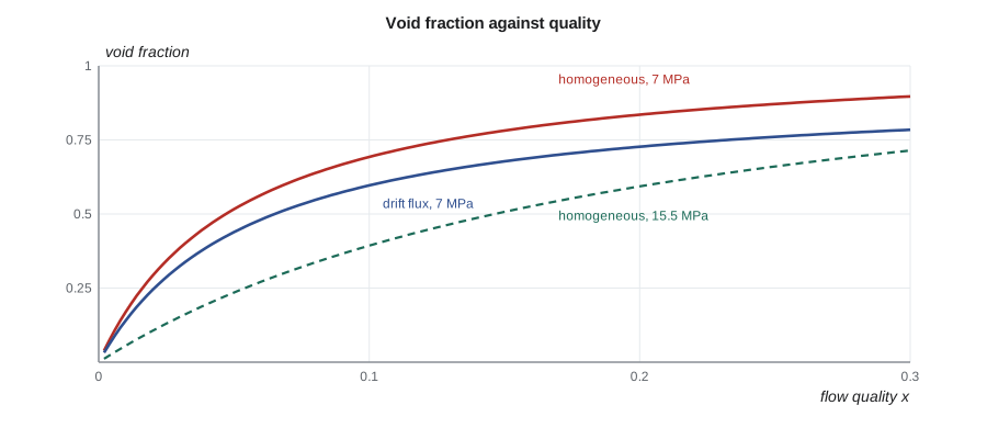
Quality is a mass ratio and void fraction is an area or volume ratio. Because steam is much less dense than water, a small quality gives a large void fraction. At 7 MPa, near BWR conditions, saturated water has a density of about 740 kg/m³ and saturated steam about 36.5 kg/m³, a ratio of about 20. A flow quality of only 5 percent corresponds to a void fraction of roughly 45 to 50 percent. At 15.5 MPa, PWR pressure, the ratio is only about 6, so the same quality gives much less void.
The equilibrium quality \(x_e\) comes straight from the energy balance of Lesson 3: once the coolant enthalpy is known, \(x_e = (h - h_f)/h_{fg}\). It is negative for subcooled liquid. The actual flow quality \(x\) can differ from \(x_e\), because near the onset of boiling, steam bubbles form on a hot wall while the bulk liquid is still subcooled. Lesson 6 explains how that subcooled boiling region is handled.
The relation between quality and void
If the two phases moved at the same velocity, the void fraction would follow from quality and densities alone. This is the homogeneous model:
In reality the vapour usually moves faster than the liquid, because it is lighter and is pushed by buoyancy and by the pressure gradient. With a slip ratio \(S\),
so slip greater than 1 lowers the void fraction for a given quality. The homogeneous model therefore overestimates void and underestimates mixture density, which matters for pressure drop, for natural circulation driving head and, in a boiling water reactor, for neutron moderation and the void reactivity feedback of NUC-300.
The drift-flux model
The drift-flux model of Zuber and Findlay is the workhorse for void fraction in vertical channels. It writes the average vapour velocity as
where \(j = j_g + j_f\) is the total volumetric flux. The distribution parameter \(C_0\), typically about 1.1 to 1.2, accounts for the tendency of bubbles to gather where the velocity is highest, near the channel centre. The drift velocity \(V_{gj}\) accounts for the local rise of vapour relative to the liquid because of buoyancy. For churn-turbulent bubbly flow,
which is about 0.15 to 0.2 m/s for water at BWR pressures. Rearranging gives the void fraction directly from the superficial velocities, \(\alpha = j_g / (C_0 j + V_{gj})\). Boiling water reactor design codes use refined drift-flux correlations fitted to bundle data across the full range of pressure, flow and void.
Worked problem
Void fraction at five percent quality
Water and steam at 7 MPa flow upward at a mass flux of 1400 kg/m²·s. At a flow quality of 0.05, compare the homogeneous void fraction with the drift-flux result for \(C_0 = 1.13\) and \(V_{gj} = 0.17\) m/s.
Show solution
- Homogeneous: \(\alpha = 1/(1 + 19 \times 36.5/740) = 1/(1 + 0.937) = 0.52\).
- Superficial velocities: \(j_g = 1400 \times 0.05/36.5 = 1.92\) m/s; \(j_f = 1400 \times 0.95/740 = 1.80\) m/s; \(j = 3.72\) m/s.
- Drift flux: \(\alpha = 1.92/(1.13 \times 3.72 + 0.17) = 1.92/4.37 = 0.44\).
- The implied slip ratio is about 1.36.
Answer: The homogeneous model gives 52 percent void; drift flux gives 44 percent. The difference changes the mixture density from about 370 to about 430 kg/m³, a change of 16 percent.
# Quality, void fraction and two-phase density: homogeneous model vs drift flux (Zuber-Findlay).
import math
rho_f, rho_g, sigma, g = 740.0, 36.5, 0.0174, 9.81    # water/steam near 7 MPa (rounded)
G = 1400.0                                             # kg/m2-s, illustrative BWR-type channel
C0 = 1.13
Vgj = 1.41 * (sigma * g * (rho_f - rho_g) / rho_f**2) ** 0.25   # churn-turbulent drift velocity
print(f"drift velocity Vgj = {Vgj:.3f} m/s, C0 = {C0}")
def alpha_hom(x): return 1 / (1 + (1 - x) / x * rho_g / rho_f)
def alpha_df(x):
    jg = G * x / rho_g; jf = G * (1 - x) / rho_f
    return jg / (C0 * (jg + jf) + Vgj)
for x in (0.01, 0.05, 0.10, 0.15, 0.20):
    ah, ad = alpha_hom(x), alpha_df(x)
    S = (x / (1 - x)) * (rho_f / rho_g) * ((1 - ad) / ad)
    rho_m = ad * rho_g + (1 - ad) * rho_f
    print(f"x = {x:4.2f}: void hom {ah:4.2f}, drift flux {ad:4.2f}, slip {S:4.2f}, mixture density {rho_m:5.0f} kg/m3")
# Homogeneous two-phase friction multiplier (same friction factor)
for x in (0.05, 0.10, 0.20):
    phi2 = 1 + x * (rho_f / rho_g - 1)
print(f"x = {x:4.2f}: homogeneous multiplier phi_lo^2 = {phi2:4.1f}")drift velocity Vgj = 0.172 m/s, C0 = 1.13 x = 0.01: void hom 0.17, drift flux 0.14, slip 1.25, mixture density 641 kg/m3 x = 0.05: void hom 0.52, drift flux 0.44, slip 1.36, mixture density 431 kg/m3 x = 0.10: void hom 0.69, drift flux 0.60, slip 1.52, mixture density 320 kg/m3 x = 0.15: void hom 0.78, drift flux 0.68, slip 1.70, mixture density 263 kg/m3 x = 0.20: void hom 0.84, drift flux 0.73, slip 1.90, mixture density 228 kg/m3 x = 0.05: homogeneous multiplier phi_lo^2 = 2.0 x = 0.10: homogeneous multiplier phi_lo^2 = 2.9 x = 0.20: homogeneous multiplier phi_lo^2 = 4.9
Flow regimes
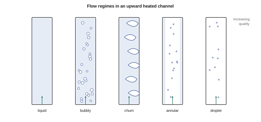
Steam and water arrange themselves in recognizable patterns, or flow regimes, that depend on the flow rates, pressure, channel size and orientation. In a vertical heated channel, the sequence is usually as follows.
| Regime | Appearance | Where it occurs |
|---|---|---|
| Bubbly | small vapour bubbles dispersed in continuous liquid | low void, just after boiling begins |
| Slug or churn | large bubbles or chaotic, frothy mixture | intermediate void; churn dominates at high pressure |
| Annular | liquid film on the wall, vapour core carrying droplets | high void, the upper part of BWR bundles |
| Mist or dispersed droplet | droplets in vapour after the wall film dries out | beyond dryout; heat transfer is poor |
In horizontal channels such as CANDU fuel channels and feeders, gravity separates the phases, and stratified and wavy regimes appear at low flows, with vapour along the top. At the high flows of normal CANDU operation the mixture stays well mixed, but during some accidents and in low-flow conditions, stratification can leave the upper elements of a bundle exposed to vapour, which is a specific concern of CANDU safety analysis.
Flow regime maps, plotted in terms of superficial velocities or of mass flux and quality, summarise where each regime occurs. System codes use them to choose the right correlations for interfacial friction, heat transfer and wall drag in each region of the plant.
Two-phase pressure drop
Friction in two-phase flow is usually larger than in liquid flow at the same mass flux, because the mixture has a higher average velocity and the interfaces add turbulence. The most common approach multiplies the friction pressure drop that the whole flow would have as liquid by a two-phase multiplier \(\phi_{lo}^{2}\):
For homogeneous flow with the same friction factor, \(\phi_{lo}^{2} = 1 + x(\rho_f/\rho_g - 1)\), which at 7 MPa and 10 percent quality is about 2.9. The Martinelli-Nelson correlation, based on separated-flow ideas and adjusted for pressure, and later correlations such as Friedel's and Chisholm's, are used in design. Acceleration pressure drop, small in liquid flow, becomes significant as the density falls along the channel. Two-phase form losses at grids and orifices are also larger than single-phase values and use their own multipliers.
Instabilities
Two-phase flow in heated channels can oscillate. Two kinds matter in reactors. A static instability, the Ledinegg excursion, occurs when the channel's pressure drop curve has a region where pressure drop falls as flow rises; the flow can then jump suddenly to a much lower value. Dynamic density-wave oscillations occur because changes in inlet flow take time to travel up the channel as changes in void, so the pressure drop responds with a delay; with the wrong combination of delay and gain, the flow oscillates with a period of one to a few seconds. Inlet orifices, which add single-phase resistance, are the main design cure. In boiling water reactors, density-wave oscillations couple with void reactivity feedback and can produce power oscillations, so BWR operating maps exclude regions of low flow and high power, and stability detection and suppression systems are installed.
Rohan notes that the BWRX-300's natural-circulation design, with a tall chimney above the core, has been analysed carefully for stability. Natural-circulation boiling water reactors are susceptible to density-wave oscillations at startup, when the chimney fills with void for the first time, and their startup procedures are designed to pass through that region safely.
Critical flow
When a pipe carrying high-pressure water breaks, the discharge flow rises as the downstream pressure falls, until it reaches a maximum and stops responding to further drops in back pressure. This choked or critical flow limits how fast coolant can leave a broken reactor system. For saturated or subcooled water, flashing to steam in the break limits the flow, and models such as the homogeneous equilibrium model, the Moody model and the Henry-Fauske model estimate it. Critical flow sets the blowdown rate in a loss-of-coolant accident, the subject of Lesson 11.
Measuring void fraction
Void fraction is hard to measure in a hot, high-pressure channel, and every two-phase correlation is only as good as the measurements behind it. Gamma densitometers send a narrow beam of gamma rays through the channel and infer the mixture density from the attenuation, using the same exponential law as in shielding. Impedance probes and wire-mesh sensors measure the electrical conductivity of the mixture across a grid of points, giving cross-sectional pictures of the flow. Quick-closing valves trap a section of flow so that the liquid inside can be weighed. Neutron and X-ray radiography give pictures of rod bundle flows in test sections. For BWR bundles, large tests with electrically heated full-scale bundles at reactor pressure have produced void data that vendors use to tune their drift-flux correlations.
In operating reactors, void cannot be measured directly. In a BWR it is inferred from the agreement between measured and calculated power distributions, since the in-core detectors respond to the local neutron flux, which depends on void. In a CANDU, channel outlet temperatures and pressures, along with the heat balance, show which channels are boiling at the outlet.
Subcooled void and the bulk energy balance
A careful designer distinguishes three quantities near the start of boiling: the equilibrium quality \(x_e\) from the energy balance, which is still negative; the true flow quality \(x\), which is slightly positive because steam is being generated at the wall; and the void fraction, which is larger than either would suggest because the bubbles hug the wall where the liquid is slow. Profile-fit models, such as Levy's or the one derived from Saha-Zuber, give the true quality as a smooth function of \(x_e\) that starts at zero at the onset of significant void and approaches \(x_e\) further downstream. Codes use this relation to compute void in the subcooled boiling region of PWR hot channels, BWR bundle entrances and CANDU channel outlets.
| Conditions | Homogeneous void | Drift-flux void (C₀ = 1.13) | Comment |
|---|---|---|---|
| 7 MPa, x = 0.05 | 0.52 | 0.44 | BWR mid-bundle |
| 7 MPa, x = 0.15 | 0.78 | 0.68 | BWR upper bundle |
| 10 MPa, x = 0.03 | about 0.25 | about 0.21 | CANDU hot channel outlet, horizontal flow differs |
| 15.5 MPa, x = 0.02 | about 0.10 | about 0.09 | PWR transient conditions |
Summary and key terms
- Flow quality is a mass ratio; void fraction is a volume ratio; a small quality gives a large void at low pressure.
- The homogeneous model assumes equal phase velocities and overestimates void; slip lowers void for a given quality.
- The drift-flux model relates void to superficial velocities through \(C_0\) and \(V_{gj}\).
- Vertical heated channels pass through bubbly, churn, annular and droplet regimes; horizontal channels can stratify.
- Two-phase friction uses a multiplier on the liquid-only pressure drop; acceleration losses become important.
- Density-wave oscillations and critical flow are characteristic two-phase phenomena with safety consequences.
- Flow quality
- The fraction of the total mass flow that is vapour.
- Void fraction
- The fraction of channel area or volume occupied by vapour.
- Slip ratio
- The ratio of vapour velocity to liquid velocity.
- Drift flux
- A model expressing vapour velocity as a distributed mixture velocity plus a local drift velocity.
- Two-phase multiplier
- The ratio of two-phase friction pressure drop to the liquid-only value at the same mass flux.
- Critical flow
- The maximum discharge rate through a break, independent of further reductions in back pressure.
Practice problems
Work each problem on paper first, then reveal the answer to check.
At 7 MPa, what homogeneous void fraction corresponds to a quality of 0.10?
Show answer
\(1/(1 + 9 \times 0.0493) \approx 0.69\).
Why does the same quality give less void at 15.5 MPa than at 7 MPa?
Show answer
The vapour-to-liquid density ratio is larger at higher pressure, so each kilogram of steam occupies less volume.
In the drift-flux model, what does C₀ greater than 1 represent?
Show answer
Bubbles concentrated where the velocity is highest, near the channel centre.
Estimate the homogeneous friction multiplier at x = 0.2 and 7 MPa.
Show answer
\(1 + 0.2 \times 19.3 \approx 4.9\).
Name the main design measure against density-wave oscillations.
Show answer
Adding single-phase inlet resistance, such as inlet orifices.
Lesson quiz · 5 questions
Score 60% or more to complete this lesson.
Create a free account to save your progress, take quizzes and earn a certificate.