
NUC-330 · Lesson 11 of 12 · 23 min
Transients and loss-of-coolant accidents
Rohan keeps a binder on his shelf labelled simply "events". Inside are the transient and accident analyses for every plant his group has worked on, each one a story told in plots of power, flow, pressure and temperature. "Steady state is where the fuel lives," he says. "Transients are where we find out whether the design was right." For the next two weeks, Hana works through the binder, starting with the gentlest events and ending with the loss-of-coolant accident.
Classifying events
Safety analysis groups events by how often they are expected and requires stricter outcomes for more frequent ones.
| Class | Expected frequency | Typical acceptance criteria |
|---|---|---|
| Anticipated operational occurrences (AOOs) | once or more in the plant life | no fuel damage: thermal limits such as dryout margin met |
| Design basis accidents (DBAs) | not expected, but credible | derived acceptance criteria on fuel sheath, fuel, channel and containment; dose limits met |
| Design extension conditions | very rare, beyond the design basis | mitigation and limits on releases; severe accident management |
In Canada, the CNSC's REGDOC-2.4.1, Deterministic Safety Analysis, sets out how licensees analyse these events, including the requirement to derive quantitative acceptance criteria that protect against fuel failure, channel failure and excessive releases. For CANDU reactors, derived acceptance criteria for design basis accidents typically include limits on fuel sheath temperature and the time spent at high temperature, on fuel centre temperature, on pressure tube integrity and on the containment.
Loss of flow
A loss of forced flow, from one pump trip up to a loss of power to all pumps, is a standard anticipated occurrence. Flow coasts down, supported by the pump flywheels, while the reactor power stays near full until a trip signal, such as low flow or low pump speed, inserts the shutdown rods. During those first seconds, heat flux stays high while flow falls, so the critical heat flux ratio drops. Fission power then falls within about a second of rod insertion, to the decay heat level, and the margin recovers as natural circulation establishes itself. The design must show that the minimum DNBR or critical power ratio stays above its limit through the dip.
A simple coastdown model writes the flow fraction as \(w(t) = 1/(1 + t/\tau)\), where \(\tau\) is a time constant of a few seconds set by the pump and flywheel inertia and the loop resistance. With \(\tau = 5\) s, flow is halved after 5 s and down to a fifth after 20 s, by which time decay heat is about 4 percent of full power.
Other anticipated transients
| Event | What changes | Main thermal concern |
|---|---|---|
| Uncontrolled control rod or bank withdrawal | reactivity and power rise | linear heat rate, DNBR or dryout |
| Loss of feedwater or turbine trip | heat sink lost, primary heats up and pressurizes | pressure limits, then DNBR |
| Steam line break (small) | overcooling, reactivity rise in PWRs | return to power, DNBR |
| Inadvertent opening of a relief valve | depressurization | DNBR as pressure falls |
| Loss of regulation (CANDU) | slow power rise | channel dryout, protected by regional overpower trips |
The loss-of-coolant accident
A loss-of-coolant accident (LOCA) is a break in the primary pressure boundary. Breaks range from small leaks, which the normal makeup system can cope with, through small breaks a few centimetres across, to the instantaneous double-ended guillotine break of the largest pipe, which has long been used as a bounding case. The phases of a large-break LOCA in a PWR are described below; CANDU and BWR phases differ in detail but follow similar physics.
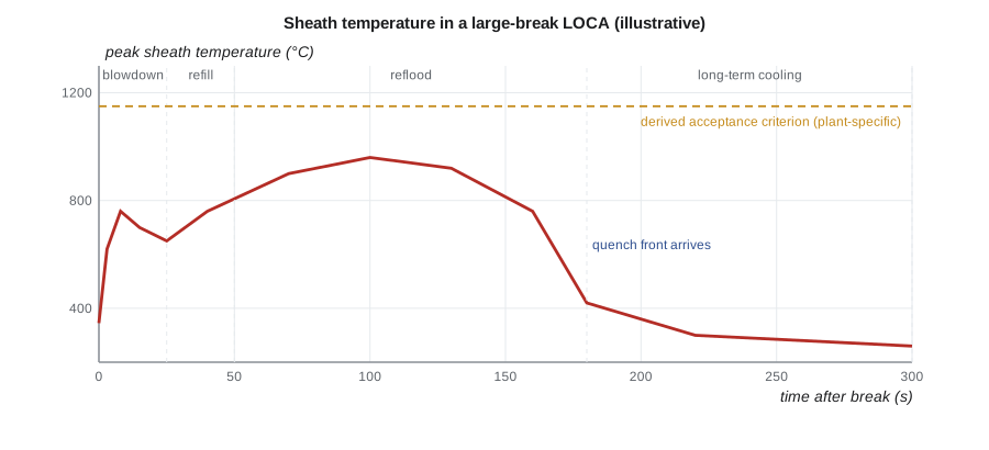
| Phase | Approximate duration | What happens |
|---|---|---|
| Blowdown | about 10 to 30 s | rapid depressurization, critical flow from the break, fluid flashes to steam, early DNB and stored energy release |
| Refill | tens of seconds | accumulators inject water, which fills the lower plenum; core is largely uncovered |
| Reflood | minutes | water rises into the core; quench front advances; steam and droplets cool the upper core |
| Long-term cooling | hours to months | pumped recirculation from the containment sump removes decay heat |
During blowdown, coolant leaves through the break at the critical flow rate of Lesson 5. The pressure falls in seconds, the coolant flashes, and the core passes DNB almost immediately. Stored energy in the fuel moves into the sheath, causing an early temperature peak. As the vessel empties, cooling relies on steam flow until the emergency core cooling system (ECCS) refills the lower plenum and refloods the core. During reflood, the sheath temperatures reach their main peak and then fall as the quench front, the boundary between wetted and dry sheath, advances upward. The ECCS has passive accumulators, pressurized tanks that inject automatically, and high- and low-pressure injection pumps; later, it recirculates water from the containment sump.
In a CANDU reactor, a large break voids the channels in the affected loop. CANDU fuel has a positive coolant void reactivity, so voiding briefly raises power until one of the two independent shutdown systems trips the reactor, within about a second or two. The emergency core cooling system then injects light water into the headers. If ECC were also unavailable, the moderator surrounding the calandria tubes, kept subcooled by its own cooling system, can remove decay heat through the pressure and calandria tube walls, and the shield tank around the calandria provides a further heat sink. This capacity to remove heat through the channel walls is one of the distinctive safety features of the design.
Acceptance criteria
For CANDU design basis LOCAs, licensees demonstrate that derived acceptance criteria are met: for example, that fuel sheath temperatures stay below values at which sheath embrittlement or failure would become likely, that fuel does not melt, that pressure tubes do not fail, and that releases and doses meet limits. The specific criteria and their technical basis are documented in each station's safety report and reviewed by the CNSC.
Worked problem
Uncooled heatup of a hot spot
After blowdown, suppose the hottest part of a rod is uncooled, starts at 600 °C, and is heated only by decay heat. The rod runs at 17.8 kW/m average with a local peaking of 2.3, and fuel plus cladding have a heat capacity of about 0.30 kJ/K per metre. Estimate the temperature after about four minutes if no cooling at all occurs.
Show solution
- Decay heat fraction near 30 s is about \(0.066 \times 30^{-0.2} = 3.5\) percent, falling slowly.
- Local decay heat \(\approx 17\,800 \times 2.3 \times 0.035 \approx 1430\) W/m at first.
- Heatup rate \(\approx 1430 / 300 \approx 4.8\) K/s initially, falling slowly as decay heat falls.
- Integrating step by step from 30 s to 240 s gives a rise of about 730 K.
Answer: About 1330 °C after four minutes with no cooling at all, above the 1204 °C limit. That is why ECCS must reflood the core within a few minutes; even partial steam cooling greatly reduces the heatup.
# Transients: pump coastdown, decay heat, and a lumped heatup of uncooled cladding.
import math
# Pump coastdown: flow fraction w(t) = 1/(1 + t/tau)
tau = 5.0
for t in (0, 2, 5, 10, 20):
    print(f"coastdown t = {t:2d} s: flow {100/(1+t/tau):5.1f} %")
# Adiabatic heatup of a fuel rod segment with decay heat only (no cooling), illustrative
q_avg = 17.8e3                  # W/m average linear heat rate at power
peak = 2.3                      # local peaking
mcp = 0.25 + 0.05               # kJ/K per metre: fuel ~0.25, clad ~0.05 (rounded, per m of rod)
T = 600.0                       # C, initial clad/fuel average after blowdown, illustrative
t, dt = 30.0, 1.0
while t < 300:
    P = q_avg * peak * 0.066 * t ** -0.2      # W/m decay heat
    T += P * dt / (mcp * 1000)
    t += dt
    if int(t) % 60 == 0: print(f"t = {int(t):3d} s: uncooled hot-spot temperature ~ {T:6.0f} C")
# Blowdown mass flow through a break: rough choked-flow estimate G ~ C*sqrt(2*rho*dp)
for d_mm in (50, 200, 700):
    A = math.pi * (d_mm / 1000) ** 2 / 4
    G = 0.6 * math.sqrt(2 * 700.0 * 15.0e6) * 0.35     # crude two-phase reduction
print(f"break {d_mm:3d} mm: initial discharge ~ {G*A:7.0f} kg/s")coastdown t = 0 s: flow 100.0 % coastdown t = 2 s: flow 71.4 % coastdown t = 5 s: flow 50.0 % coastdown t = 10 s: flow 33.3 % coastdown t = 20 s: flow 20.0 % t = 60 s: uncooled hot-spot temperature ~ 727 C t = 120 s: uncooled hot-spot temperature ~ 948 C t = 180 s: uncooled hot-spot temperature ~ 1147 C t = 240 s: uncooled hot-spot temperature ~ 1333 C t = 300 s: uncooled hot-spot temperature ~ 1509 C break 50 mm: initial discharge ~ 60 kg/s break 200 mm: initial discharge ~ 956 kg/s break 700 mm: initial discharge ~ 11712 kg/s
Small-break LOCAs
Small breaks are slower and in some ways harder to analyse. The system depressurizes gradually; the reactor trips; the pumps may be tripped by procedure; and the coolant drains by gravity to the lowest points. The behaviour depends on where the break is and on the natural circulation and reflux condensation modes of Lesson 10. In PWRs, water can be held up in the pump suction loop seals until they clear, and the core level can dip temporarily. The 1979 Three Mile Island Unit 2 accident began as a small-break LOCA through a stuck-open pressurizer relief valve, compounded by misleading indications that led operators to reduce injection; its lessons transformed operator training, control room design and small-break analysis. NUC-410 covers it in detail.
Reactivity-initiated accidents
A rapid insertion of reactivity, such as the ejection of a control rod in a PWR or a rod drop in a BWR, produces a sharp power pulse lasting tens of milliseconds. The energy deposited in the fuel before Doppler feedback stops the excursion can heat the pellets and load the cladding very quickly. Acceptance criteria are expressed as limits on the fuel enthalpy rise and on cladding failure thresholds, and they have been revised as tests on high-burnup fuel showed lower failure thresholds than earlier data suggested.
Conservatism, best estimate and uncertainty
Early LOCA analyses stacked conservative assumptions on each other: high decay heat, conservative heat transfer, worst-case break, single failure in the ECCS. Modern best-estimate plus uncertainty (BEPU) methods use realistic models and propagate uncertainties statistically, often showing that a criterion is met at the 95th percentile with 95 percent confidence. Both approaches are accepted when properly justified. They are discussed further in Lesson 12, because the codes are where the methods live.
Emergency core cooling in different designs
| Design | High-pressure stage | Passive or intermediate stage | Long-term stage |
|---|---|---|---|
| Large PWR | high-pressure safety injection pumps | nitrogen-pressurized accumulators | low-pressure injection, then sump recirculation |
| Large BWR | high-pressure core spray or injection | automatic depressurization system enables low-pressure injection | low-pressure core spray and injection, suppression pool cooling |
| CANDU | high-pressure injection from accumulator tanks or pumps | medium-pressure injection | low-pressure recovery from the building sump |
| BWRX-300 | isolation condensers keep the reactor inventory | large isolation valves limit loss of inventory | passive containment cooling; long-term makeup |
Different designs reach the same goal in different ways. Large light water reactors rely on several stages of injection, so that water is always being added at whatever pressure the system has reached. A boiling water reactor that cannot inject at high pressure deliberately depressurizes, through an automatic depressurization system, so that its low-pressure systems can work. CANDU emergency core cooling injects into the headers in stages and then recirculates from the building sump. The BWRX-300 takes a different approach to large breaks: its design places isolation valves directly on the vessel nozzles, so that a pipe break outside them can be isolated and the reactor inventory kept, with isolation condensers removing decay heat. In every case, the analysis must show the acceptance criteria are met assuming the worst single failure in the safety systems.
What the plots in a safety report show
Hana learns to read a LOCA analysis by its plots. Primary pressure falls from operating pressure toward containment pressure within tens of seconds for a large break, or over many minutes for a small one. Break flow starts at the critical flow rate and falls as pressure drops. Core collapsed liquid level shows when the core uncovers and when it recovers. Peak cladding temperature rises during blowdown, may dip, rises again during refill and peaks during reflood before falling as the quench front passes. Containment pressure rises and then falls as heat sinks and cooling systems absorb energy. For each plot, the analyst asks what physics drives the shape and whether the timing makes sense, the same habit Rohan has drilled into her with hand calculations throughout the course.
Worked problem
Energy in the break flow
During the first ten seconds of a large break, about 8000 kg of coolant leaves the system with an average specific enthalpy of about 1.4 MJ/kg relative to the containment's reference state. Roughly how much energy enters the containment, and why does it matter?
Show solution
- Energy \(\approx 8000 \times 1.4\times10^{6} = 1.1\times10^{10}\) J, or about 11 GJ.
- Spread over ten seconds, that is an average of about 1.1 GW entering the containment atmosphere, mostly as steam.
Answer: About 11 GJ in ten seconds. The rate of energy release sets the containment pressure peak, which is why containment analyses use the same mass and energy release calculations as the core cooling analyses.
Summary and key terms
- Events are classed by frequency, with stricter acceptance criteria for more frequent ones.
- Loss-of-flow transients lower DNBR or critical power ratio until the reactor trips and natural circulation takes over.
- A large-break LOCA passes through blowdown, refill, reflood and long-term cooling; ECCS refloods the core.
- CANDU safety analysis uses derived acceptance criteria under REGDOC-2.4.1; the moderator provides a backup heat sink.
- Small breaks depend on natural circulation, gravity drainage and operator actions; Three Mile Island began as one.
- Reactivity-initiated accidents are judged by fuel enthalpy and cladding failure thresholds; BEPU methods quantify uncertainty.
- Anticipated operational occurrence
- An event expected one or more times during the life of a plant.
- Loss-of-coolant accident
- A break in the primary pressure boundary that releases coolant.
- Blowdown
- The rapid depressurization phase after a break.
- Reflood
- The phase in which emergency coolant rises into the core and quenches the fuel.
- Quench front
- The boundary between rewetted and dry sheath surfaces during reflood.
- Best estimate plus uncertainty
- An analysis approach using realistic models with statistically quantified uncertainties.
Practice problems
Work each problem on paper first, then reveal the answer to check.
With τ = 4 s, what flow fraction remains 12 s after a pump trip?
Show answer
\(1/(1 + 3) = 25\) percent.
Why does DNBR fall in a loss-of-flow transient before the trip?
Show answer
Heat flux stays near full while flow falls, so CHF falls toward the actual heat flux.
Name the four phases of a large-break PWR LOCA.
Show answer
Blowdown, refill, reflood and long-term cooling.
Why does a CANDU large LOCA cause a brief power rise?
Show answer
Voiding the channels adds positive reactivity until a shutdown system trips.
What does the quench front mark?
Show answer
The boundary between wetted (nucleate boiling) and dry (film boiling) sheath during reflood.
Lesson quiz · 5 questions
Score 60% or more to complete this lesson.
Create a free account to save your progress, take quizzes and earn a certificate.