
NUC-330 · Lesson 1 of 12 · 23 min
Heat generation in fuel
After her radiation protection teaching term, Hana Okoye has one more rotation before she settles into the core physics group at Meridian Nuclear Engineering: six months with the thermal-hydraulics team led by Dr. Rohan Desai. Rohan's group is answering two questions for Ontario Power Generation (OPG). The first is how much margin to fuel channel dryout remains in the refurbished Darlington units as their pressure tubes age. The second is how the BWRX-300 small modular reactor being built at the Darlington New Nuclear site keeps its core cool with no reactor coolant pumps at all. "Reactor physics tells you where the fissions happen," Rohan tells her on her first morning. "Thermal hydraulics tells you whether the fuel survives them. Every limit you will meet in this group starts with one number: how much heat each piece of fuel makes."
This course follows that work. It is the engineering bridge between the neutron physics of NUC-300 and the safety analysis of later courses. It uses the heat transfer and fluid mechanics of MEC-340 and MEC-270 and applies them to the unusual conditions inside a reactor: very high heat fluxes, coolant at high pressure and close to boiling, two-phase flow in long heated channels, and a heat source that does not switch off when the reactor shuts down.
Where fission energy goes
Each fission of uranium-235 releases about 200 MeV. Not all of it appears as heat in the fuel. The kinetic energy of the two fission fragments, about 165 to 170 MeV, is deposited within a few micrometres of the fission site, so it heats the fuel pellet itself. The prompt gamma rays and the kinetic energy of the fission neutrons are deposited partly in the fuel and partly in the coolant, moderator and structures, because gammas and fast neutrons travel centimetres before they are absorbed or slowed down. Beta particles from fission products are absorbed mostly in the fuel. The antineutrinos, carrying roughly 10 MeV, escape the reactor entirely and contribute nothing. Neutron capture in fuel, coolant and structures adds several MeV of capture gamma energy per fission, which partly makes up for the neutrinos.
| Energy carrier | Approximate energy per fission (MeV) | Where it is deposited |
|---|---|---|
| Fission fragment kinetic energy | 165 to 170 | fuel, within micrometres |
| Prompt gamma rays | about 7 | fuel, coolant, moderator and structures |
| Fission neutron kinetic energy | about 5 | mostly moderator and coolant during slowing down |
| Beta particles from fission products | about 7 | fuel |
| Delayed gamma rays from fission products | about 6 | fuel and surroundings |
| Antineutrinos | about 10 | escape, not recoverable |
| Capture gamma rays (non-fission captures) | several | wherever the capture occurs |
Designers usually say that about 97 percent of the recoverable energy is deposited in the fuel and the rest in the coolant and moderator. The split matters more in a CANDU reactor than in a light water reactor. In a CANDU the heavy water moderator is a separate low-pressure tank, the calandria, and it receives roughly 4 to 5 percent of the reactor's thermal power from neutron slowing-down and gamma heating. That heat has to be removed by its own moderator cooling system, which later turns out to be an important safety heat sink. In a pressurized water reactor the coolant is also the moderator, so heat deposited directly in the water simply joins the heat conducted out of the fuel rods.
Volumetric heat generation
The local rate of heat generation in fuel follows directly from reactor physics. If \(\phi\) is the neutron flux, \(\Sigma_f\) the macroscopic fission cross section of the fuel and \(E_f\) the energy deposited per fission, the volumetric heat generation rate is
With \(E_f\) in joules, \(\Sigma_f\) in reciprocal metres and \(\phi\) in neutrons per square metre per second, \(q'''\) comes out in watts per cubic metre. In a power reactor the values are enormous: a few hundred megawatts per cubic metre of fuel at the hottest points. That is far higher than in a fossil-fired boiler, and it is the root of most thermal-hydraulic design challenges. Heat has to leave a pellet only a centimetre or so across through a gap, a thin metal sheath and a boundary layer of coolant, and it has to do so steadily for years.
Because \(q'''\) is proportional to the flux, its shape across the core is the flux shape from NUC-300, modified by fuel loading, burnup and control devices. Thermal-hydraulic engineers rarely work with \(q'''\) directly. They prefer three related quantities that suit the geometry of a fuel rod or element.
| Quantity | Symbol and unit | Definition | Typical use |
|---|---|---|---|
| Volumetric heat generation | q''' (W/m³) | heat per unit fuel volume | conduction inside the pellet |
| Linear heat rate | q' (kW/m) | q''' × pellet cross-section area | fuel performance limits |
| Surface heat flux | q'' (MW/m²) | q' ÷ sheath outer circumference | boiling and critical heat flux |
| Rod, element or channel power | kW or MW | integral of q' over the length | channel and core heat balances |
For a pellet of radius \(R\), \(q' = \pi R^{2} q'''\), and for a sheath of outer diameter \(D\), \(q'' = q'/(\pi D)\). The linear heat rate is especially useful because, as Lesson 2 shows, the temperature difference across the fuel pellet depends on \(q'\) and not on the pellet radius.
From core power to the average fuel rod
A useful first calculation is the average linear heat rate. Take the core thermal power, multiply by the fraction deposited in the fuel, and divide by the total length of fuel in the core.
Worked problem
Average linear heat rate in two reactor types
A four-loop pressurized water reactor has a thermal power of 3411 MW, 193 fuel assemblies of 264 rods each and an active fuel length of 3.66 m. A CANDU bundle of 37 elements, each about 0.495 m long, produces 900 kW at the hottest point of the core. Find the average linear heat rate in each case, taking 97.4 percent of the power to be deposited in the fuel.
Show solution
- PWR: number of rods \(= 193 \times 264 = 50\,952\); total fuel length \(= 50\,952 \times 3.66 = 186\,500\) m.
- \(q'_{\text{avg}} = 0.974 \times 3411 \times 10^{6} / 186\,500 = 17.8\) kW/m.
- CANDU bundle: \(q' = 900\,000 / (37 \times 0.495) = 49\) kW/m, averaged over the 37 elements of that bundle.
Answer: About 18 kW/m for the average PWR rod and about 49 kW/m for elements in a high-power CANDU bundle . CANDU elements are larger in diameter and are rated more highly, which is one reason CANDU fuel centre temperatures are high even though the coolant is cooler.
The comparison is not unfair to either design. A CANDU element has a pellet about 12 mm across, compared with about 8 mm in a PWR rod, so more fuel per metre is available to carry the heat. The bundle is also only half a metre long and is replaced while the reactor runs, so it never spends long at the highest powers.
Axial and radial power shapes
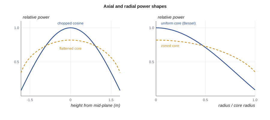
Reactor physics gives a flux that peaks in the middle of the core and falls toward the edges. For a bare cylindrical core with uniform fuel, one-group diffusion theory gives a cosine shape along the axis and a Bessel-function shape across the radius:
Here \(R_e\) and \(H_e\) are the extrapolated radius and height, slightly larger than the physical core because the flux does not fall to zero exactly at the core boundary. Because the fuel stops before the extrapolated boundary, the actual axial shape is a chopped cosine. Real cores are flatter than this ideal: fuel management, burnable absorbers, enrichment zoning in light water reactors and differential fuelling and adjuster rods in CANDU reactors are all used to flatten the power so that more of the fuel runs close to the maximum allowed rating.
Peaking factors
Thermal limits are set by the hottest fuel, not the average. Designers therefore describe the power distribution with peaking factors, ratios of a local value to the core average.
| Factor | Definition | Typical size |
|---|---|---|
| Axial peaking F_z | maximum q' along a rod ÷ average q' along that rod | 1.3 to 1.6 |
| Radial or assembly peaking F_r | average q' of the hottest rod ÷ core average | 1.3 to 1.6 |
| Heat flux hot channel factor F_q | peak local q' anywhere ÷ core average q' | about 2 to 2.5 in a PWR |
| Enthalpy rise factor F_ΔH | integrated power of the hottest rod ÷ average rod | about 1.5 to 1.65 in a PWR |
For a chopped cosine, the axial peaking factor is the ratio of the peak to the mean of the cosine over the fuelled length. If the fuelled height is \(H\) and the extrapolated height \(H_e\),
For \(H = 3.66\) m and \(H_e = 3.86\) m, \(F_z \approx 1.49\). Combined with a radial factor of 1.55, the local peak is about 2.3 times the core average, so the hottest point in the PWR runs at about 41 kW/m. Plant technical specifications limit the measured value of \(F_q\) and \(F_{\Delta H}\), and in-core instruments check them regularly.
In a CANDU reactor the equivalent limits are on channel power and bundle power. With 480 channels in a Darlington unit, a typical maximum channel power is about 7 MW and a typical maximum bundle power about 900 kW. Because fuelling continues during operation, the operator manages channel powers day by day with the fuelling schedule and the zone controllers, and the regional overpower protection system trips the reactor if detector readings show any channel approaching its dryout limit.
Decay heat
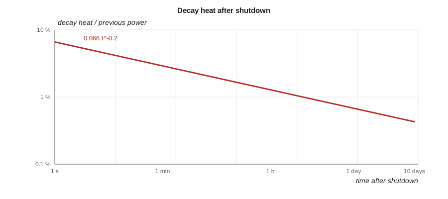
When a reactor shuts down, fission stops within seconds, but the radioactive fission products keep decaying and keep releasing heat. Immediately after shutdown the decay heat is about 6 to 7 percent of the previous operating power. It falls quickly at first and then slowly: about 1 percent after an hour and about half a percent after a day. For a 3400 MW core, half a percent is still 17 MW, enough to boil away tens of tonnes of water per hour if cooling is lost.
A simple estimate for a reactor that has operated for a long time is the Way-Wigner formula,
with \(t\) in seconds after shutdown. It is good to within a factor of about two over a wide range of times and is useful for quick checks. Licensing analyses use standards such as the ANS 5.1 decay heat standard, which tabulates the contribution of each fissioning nuclide, accounts for operating history and adds actinide decay from uranium-239 and neptunium-239. Decay heat is the reason reactors need cooling systems that work after shutdown, the reason natural circulation matters, and the central driver of loss-of-coolant analysis in Lesson 11.
# Heat generation: average linear heat rate, axial cosine shape, peaking and decay heat.
import math
# Illustrative PWR core (rounded public-domain values for a large four-loop plant)
P_th = 3411e6            # W thermal
frac_fuel = 0.974        # fraction of energy deposited in the fuel
n_rods, L = 50952, 3.66  # fuel rods and active length (m)
q_avg = P_th * frac_fuel / (n_rods * L)
print(f"PWR average linear heat rate  q' = {q_avg/1000:5.1f} kW/m")
# Illustrative CANDU bundle: 37 elements, 0.495 m long
P_bundle, n_el, L_b = 900e3, 37, 0.495
print(f"CANDU bundle at 900 kW: element average q' = {P_bundle/(n_el*L_b)/1000:5.1f} kW/m")

# Chopped cosine axial shape: q'(z) = q'max * cos(pi*z/Le), z from core mid-plane
Le = L + 2 * 0.10        # extrapolated length (m), illustrative
mean_over_core = (Le / (math.pi * L)) * 2 * math.sin(math.pi * L / (2 * Le))
Fz = 1 / mean_over_core
print(f"axial peaking factor (chopped cosine) Fz = {Fz:4.2f}")
F_r = 1.55               # illustrative radial (rod-to-core) peaking
print(f"total peaking Fq ~ Fz*Fr = {Fz*F_r:4.2f}; peak q' = {q_avg*Fz*F_r/1000:5.1f} kW/m")

# Decay heat after shutdown, Way-Wigner style estimate (infinite prior operation)
def decay_fraction(t):   # t in seconds after shutdown
    return 0.066 * t ** -0.2
for t in (1, 10, 60, 3600, 86400):
print(f"t = {t:6d} s: decay heat ~ {100*decay_fraction(t):4.2f} % of full power")PWR average linear heat rate q' = 17.8 kW/m CANDU bundle at 900 kW: element average q' = 49.1 kW/m axial peaking factor (chopped cosine) Fz = 1.49 total peaking Fq ~ Fz*Fr = 2.32; peak q' = 41.3 kW/m t = 1 s: decay heat ~ 6.60 % of full power t = 10 s: decay heat ~ 4.16 % of full power t = 60 s: decay heat ~ 2.91 % of full power t = 3600 s: decay heat ~ 1.28 % of full power t = 86400 s: decay heat ~ 0.68 % of full power
Heat generation outside the fuel
Some heat appears where there is no fuel. Gamma rays deposit energy in pressure tubes, calandria tubes, the reactor vessel wall, core barrels and control devices. Fast neutrons slowing down in the moderator heat it directly. These sources are small fractions of the total, but they matter for components that are cooled weakly or that must stay within material limits, such as a PWR vessel wall facing the core or the CANDU calandria shell. Engineers calculate them with gamma transport and heating codes and include them in the cooling design of each component.
Burnup and changing power shapes
Heat generation changes over a fuel's life. As uranium-235 is consumed and plutonium builds up, the local power in a given fuel element changes; fission products absorb neutrons and shift the flux; and burnable absorbers in light water reactor fuel burn out. In a CANDU reactor, a fresh bundle pushed into a channel is at first more reactive than the bundles around it, giving a short-lived power boost known as a refuelling ripple. Thermal-hydraulic limits must be met at every point in the cycle, so designers check the power shapes at many burnup steps, not just at the start.
Hana's first assignment is modest. Rohan gives her the core power, the number of fuel rods or elements, and a few peaking factors, and asks her to tell him the linear heat rate at the hottest point and the decay heat one minute, one hour and one day after a trip. "If you can get those right in your head," he says, "you will catch half the mistakes anyone makes with the big codes."
Summary and key terms
- About 200 MeV is released per fission of uranium-235; roughly 97 percent of the recoverable energy is deposited in the fuel.
- Volumetric heat generation is \(q''' = E_f \Sigma_f \phi\); designers mostly work with linear heat rate \(q'\) and surface heat flux \(q''\).
- The average PWR rod runs near 18 kW/m; high-power CANDU elements run near 50 kW/m.
- Ideal power shapes are cosine axially and Bessel radially; real cores are flattened by fuel management.
- Peaking factors relate the hottest local values to core averages and are limited in technical specifications.
- Decay heat starts near 6 to 7 percent of full power and falls slowly; it must always be removed.
- Linear heat rate
- Heat produced per unit length of a fuel rod or element, usually in kW/m.
- Surface heat flux
- Heat leaving the sheath per unit surface area, usually in MW/m².
- Chopped cosine
- The axial power shape of a finite core whose fuel stops short of the extrapolated boundary.
- Peaking factor
- The ratio of a local maximum to the corresponding average value.
- Enthalpy rise factor
- The ratio of the integrated power of the hottest rod or channel to the average.
- Decay heat
- Heat released by radioactive decay of fission products and actinides after shutdown.
Practice problems
Work each problem on paper first, then reveal the answer to check.
A core of 2000 MW has 40 000 rods 3.6 m long. Estimate the average linear heat rate, taking 97 percent to the fuel.
Show answer
\(0.97 \times 2000 \times 10^{6} / 144\,000 \approx 13.5\) kW/m.
A rod has a sheath diameter of 9.5 mm and a local linear heat rate of 40 kW/m. What is the surface heat flux?
Show answer
\(40\,000 / (\pi \times 0.0095) \approx 1.34\) MW/m².
Estimate the decay heat 10 minutes after shutdown of a 3000 MW core.
Show answer
\(0.066 \times 600^{-0.2} \approx 1.9\) percent, about 57 MW.
Why is moderator heating more important in a CANDU than in a PWR?
Show answer
The CANDU moderator is a separate low-pressure system that must be cooled on its own; it receives about 4 to 5 percent of the power.
Does flattening the radial power shape raise or lower the allowable core power for a fixed peak limit?
Show answer
It raises it, because the average can approach the limit more closely.
Lesson quiz · 5 questions
Score 60% or more to complete this lesson.
Create a free account to save your progress, take quizzes and earn a certificate.