
IRW-320 · Lesson 2 of 12 · 22 min
Reading shop drawings
▶ Video coming soon A video version of this lesson is on the way.
On Tuesday morning, November 10, it rained until ten, so Lionel spread the Ashcroft shop drawings on the plan table in Tallcorn's site trailer and taught Shay to read them. "A raising gang reads erection drawings," he said. "Piece marks, column lines, elevations. We read those too, but for misc, the shop drawing is the drawing. It shows every piece the way the shop made it, and if it's wrong, it's wrong in steel." Rhea was at the other end of the table checking the railing drawings against the field dimensions she had taken on Monday.
This lesson explains what misc and ornamental shop drawings are, how they are prepared and reviewed, how to read the views, dimensions, symbols and notes on them, how field dimensions feed back into them, and what to do when the steel and the building do not agree.
What a shop drawing is
The architect's and engineer's drawings, the contract drawings, show what the building must be: where a stair goes, how high the guard is, what the canopy looks like and what loads it must carry. They do not show how to make it. The fabricator prepares shop drawings that show each piece exactly as it will be made: every plate, every bar, every weld, every hole, with its size, material and finish. The erector installs from the shop drawings, or from erection drawings drawn from them.
Shop drawings for misc metals are prepared by the fabricator's detailer, often with the fabricator's engineer where the specification makes the fabricator responsible for designing connections or railing systems. At Ashcroft, section 05 52 00 required the railings to be designed by a professional engineer for the code loads, so Stonegate's shop drawings carried their engineer's seal for the railings. The stairs and canopy were designed by the building's engineer of record, Fenwick Structural, and Stonegate only detailed them.
- Contract drawings say what the finished work must be and do.
- Shop drawings say exactly how each piece is made.
- Erection or installation drawings say where each piece goes and how it is connected in the field.
- Calculations, where required, show that the fabricator's design meets the loads.
The review cycle
Shop drawings go through a review before fabrication. The fabricator submits them to the general contractor, who checks them against the contract and passes them to the architect and engineer. The design team reviews them for general conformance with the design intent and returns them with a stamp. The words on the stamp vary, but there are usually four outcomes.
| Stamp | Meaning | What happens next |
|---|---|---|
| Reviewed, no exceptions | The drawing conforms to the design intent | Fabrication may start |
| Reviewed as noted | It conforms if the noted corrections are made | Fabricate with the corrections; some offices want a corrected copy |
| Revise and resubmit | Changes are needed and the drawing must come back | Do not fabricate the affected pieces |
| Rejected | It does not conform | Start again |
The review does not make the design team responsible for the fabricator's dimensions or quantities, and every stamp says so in some form. The fabricator and the erector remain responsible for fitting the work to the building. That is why the erector checks the shop drawings against the field, too.
At Ashcroft, Stonegate submitted the stair shop drawings on August 24 and got them back on September 4 reviewed as noted, with two notes: the guard height on the landings was to be measured from the landing surface, not the nosing line, and the stringer connection at level 2 was to match a revised beam elevation. The canopy drawings were first returned revise and resubmit on September 18, because the outrigger connection did not match the embed plate the engineer had shown, and were approved after resubmission on October 14. Shay found both stamps on the drawings, with the dates, in red.
Lionel insisted that the crew work only from the latest reviewed set. Superseded sheets were marked void and pulled from the gang box. "Two versions of a canopy drawing on site is how you get a canopy that fits the old embed," he said.
The parts of a shop drawing
Every sheet has a title block with the project, the fabricator, the drawing number, the revision and its date, the detailer and the checker. The revision block lists every change, and a cloud with a revision triangle on the drawing shows where each change was made. Before reading a sheet, Lionel always looked at the revision block first. Then he read the general notes: material grades, finishes, weld types, bolt types and the drawings this sheet relies on.
The views on a misc sheet usually include a plan, one or more elevations, sections cut through the piece, and enlarged details of connections. A stair sheet, for example, shows the stair in plan with its run and landing, an elevation along each stringer with the riser and tread dimensions, a section through a tread showing the pan and nosing, and details of each end connection.
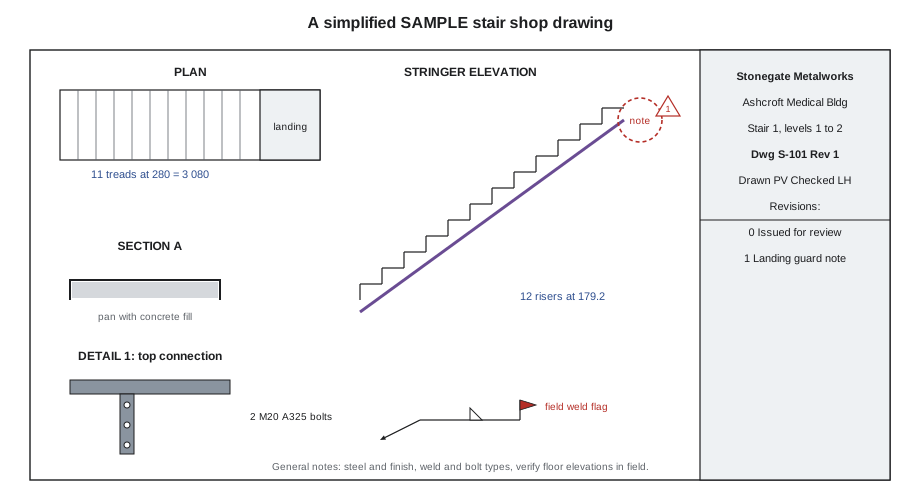
Dimensions and how they are written
Misc shop drawings are dimensioned more densely than erection drawings, because every hole and every bend must be located. Some habits make them easier to read.
- Dimensions in Canada are almost always in millimetres, with no unit written. A dimension of 1 070 means 1,070 mm; the space instead of a comma is common on metric drawings.
- Running dimensions measure from one datum, such as a column line or the top of a slab, so that errors do not add up. Chain dimensions measure from one feature to the next; the sum of a chain should equal the overall dimension, and checking that is a good way to catch an error.
- Elevations are given from the project datum, the same one the raising gang used, and the misc drawing should use the same values as the erection drawings for the same steel.
- Dimensions marked as field dimensions, or with a note such as "verify in field", are the erector's to confirm before fabrication.
- A dimension shown in brackets or marked as reference is for information only and is not to be used for fabrication.
Rhea added one habit of her own: she circled every dimension on the drawing that depended on another trade's work, such as the depth of a concrete slab or the face of a masonry wall, because those were the ones that would be wrong on site.
Symbols and notes
Shop drawings use standard symbols. Weld symbols follow the national standard, CSA W59: the reference line, the arrow, the weld type, its size and length, field-weld flags and all-around circles. A field-weld flag matters most to the erector, because it marks a weld the misc crew will make on site rather than one the shop has already made. Bolts are shown with their size, grade and type. Holes are given by diameter, with slots by their width and length.
Finish notes say what the surface will be: galvanized, shop primed, painted, powder coated, stainless with a specified finish, or bare. Material notes give the grade of steel, the alloy of stainless or aluminum and the specification of pipe and tube. A careful installer reads the finish note before handling a piece, because it tells him what must not be scratched, welded or ground.
Field dimensions
Misc steel has to fit a building that was built by other trades to their own tolerances. A stair stringer must land on a beam whose elevation may differ from the drawing by a few millimetres; a railing must meet a wall that was built a little out of plumb; a canopy must bolt to an embed plate that moved when the concrete was placed. So before the shop builds, the erector measures the actual building and sends field dimensions back to the fabricator.
Field measuring follows a few rules. Measure from the same datum the drawings use. Measure every dimension the drawing marks as a field dimension, and any dimension Rhea would have circled. Record the measurement, the date, who measured and the instrument used. Send it in writing. And when a field dimension is far from the drawing, report it as a problem to be solved, not just a number.
Worked problem
Checking a chain of dimensions
A railing shop drawing for the Stair 1 landing shows a chain of post spacings of 1 200, 1 200, 1 150 and 450 mm, from the wall to the end post, with an overall dimension of 4 050 mm. Rhea measured 4 012 mm on site from the finished wall to the stringer end. Does the chain add up, and what should she report?
Show solution
- Sum of the chain: 1 200 + 1 200 + 1 150 + 450 = 4 000 mm.
- The overall is shown as 4 050 mm, so the drawing itself is 50 mm inconsistent.
- The field measurement is 4 012 mm, which is 38 mm less than the overall and 12 mm more than the chain.
Answer: The Canadian drawing has an internal error: its chain does not add up to its overall. Rhea reported both the error and her field dimension, and asked Paulette to set the last space so the end post lands 50 mm from the stringer end, as the detail required. Catching a chain that does not add up is one of the cheapest checks an installer can make.
When the steel and the building disagree
Sooner or later every misc crew finds a piece that does not fit. The response matters more than the problem. The wrong responses are well known: cut it, heat it, bend it, slot it or weld a plate to it on the spot, without asking. Each of these can weaken a piece, ruin its finish, void the fabricator's design or simply move the error somewhere else.
The right response is to stop, measure, and report. Lionel's crew filled in a short field report: what does not fit, by how much, where, a photo with a tape in it, and a suggested fix. The foreperson sends it to the general contractor, who sends it on as a request for information to the design team or to the fabricator. Small fixes that do not affect strength, such as a slightly longer shim stack within the shop drawing's limits, are within the erector's authority. Anything that changes a connection, a load path, a guard height or an opening size needs the engineer's or architect's answer in writing.
On Monday, Rhea had found one such problem: clip angle C-7 at the level 3 edge beam for the curtain wall was 32 mm (1 1/4 in) lower than the drawing showed. Lionel's report went to Priscilla Hahn at Tallcorn that afternoon. Lesson 12 follows what happened next.
Reading a canopy drawing
Before the rain stopped, Lionel walked Shay through the approved canopy drawing, sheet C-2 revision 2. The canopy was 9.0 m (30 ft) wide and projected 2.4 m (8 ft) from the face of the entrance lobby. Four steel outriggers of rectangular tube cantilevered from the lobby frame, bolted to plates welded to the columns and the edge beam. A steel edge channel and three intermediate purlins carried a metal deck, with a roof membrane and an aluminum soffit by others. Shay found the field-weld flags at the outrigger end plates, the bolt callouts, the slotted holes at the purlin connections that would let the canopy move with temperature, and the finish note: hot-dip galvanized, then painted in the field by the painting contractor.
"Now tell me what you'd check before we set the first outrigger," Lionel said. Shay listed the plate locations on the columns, the elevation of the outrigger top against the drawing, the bolt sizes on site, and the slope the drawing called for so that the canopy would drain toward its back gutter. Lionel added one more: the revision. Sheet C-2 revision 1 had shown a different plate. "Check that the plate on the column is the one revision 2 shows. They made it on the old drawing once before."
Shop drawings and the schedule
Shop drawings take time, and that time sits at the front of the misc schedule. A typical cycle is two to three weeks for the detailer to draw, one to two weeks for the review, a few days for corrections, and then two to six weeks for fabrication and finishing, longer if the pieces are galvanized or powder coated off site. At Ashcroft, the canopy took from August to early November because its first submission came back revise and resubmit. Lionel kept a simple log of every submission: the drawing number, the date it went out, the date it came back, the stamp and what was needed. The log told him which pieces would be late weeks before they were, and gave Priscilla Hahn something to show the owner when the schedule was questioned.
Field dimensions fit into the same cycle. Some cannot be taken until other trades have built their work, such as the finished wall a handrail meets or the slab edge a guard bolts to. For those, the shop drawing is reviewed with the field dimensions left open, the shop prepares everything else, and the final dimensions go in when the field is ready. Rhea called these hold dimensions and marked them on the drawing in a different colour so nobody fabricated them by mistake.
Common mistakes
MistakeWorking from an old revision.
InsteadCheck the revision block and work only from the latest reviewed set; void old sheets.
MistakeFabricating or installing from a revise-and-resubmit drawing.
InsteadWait for an approved or reviewed-as-noted stamp.
MistakeAssuming the review makes the design team responsible for dimensions.
InsteadThe fabricator and erector remain responsible for fit; check field dimensions.
MistakeNot checking that a chain of dimensions adds up.
InsteadAdd the chain and compare it to the overall on every sheet you use.
MistakeCutting or bending a piece that does not fit.
InsteadStop, measure, photograph and report; get a written answer for any change to a connection or a code dimension.
Summary and key terms
- Contract drawings say what the work must be; shop drawings say exactly how each piece is made.
- Shop drawings are reviewed for conformance with the design intent; the stamp decides whether fabrication may start.
- Read the revision block and general notes first, then the views, dimensions, symbols and finish notes.
- Running dimensions avoid accumulated error; chain dimensions should add up to the overall.
- Field dimensions are measured, recorded and sent in writing before fabrication.
- When steel and building disagree, stop, measure, report and wait for a written answer to anything that affects strength or a code dimension.
- Shop drawing
- A fabricator's drawing showing exactly how each piece is made.
- Contract drawings
- The design team's drawings showing what the finished work must be.
- Revision cloud
- A cloud drawn around a change on a drawing, with a triangle giving the revision number.
- Field dimension
- A dimension measured on site and sent to the fabricator before fabrication.
- Field-weld flag
- A flag on a weld symbol marking a weld made on site.
- Request for information
- A written question to the design team about a problem or an unclear detail.
Practice problems
Work each problem on paper first, then reveal the answer to check.
A chain reads 900, 900, 900 and 300 mm with an overall of 3 000. Is it consistent?
Show answer
Yes: 900 + 900 + 900 + 300 = 3 000.
What does a field-weld flag tell the erector?
Show answer
That the weld is made on site, not in the shop.
A drawing is stamped revise and resubmit. May the shop fabricate it?
Show answer
No, not the affected pieces.
What should a field report include?
Show answer
What does not fit, by how much, where, a photo with a tape and a suggested fix.
Why measure from the same datum as the drawings?
Show answer
So that the measurements can be compared directly without accumulated error.
Lesson quiz · 5 questions
Score 60% or more to complete this lesson.
Create a free account to save your progress, take quizzes and earn a certificate.