
IRW-310 · Lesson 7 of 12 · 21 min
Bridges and girder erection
▶ Video coming soon A video version of this lesson is on the way.
In IRW-120, Carla mentioned a lift from 2023: two cranes setting a pedestrian bridge girder over a rail line. On November 6 she told the rest of the story. The bridge was a 38 m (125 ft) span of two steel plate girders, each weighing about 18,000 kg (40,000 lb), carrying a walkway over a commuter rail corridor. The girders had to go up in one night, during a rail possession, a window when the railway stopped trains and switched off nothing more than it had to. "Four hours," she said. "Two cranes, two girders, cross-frames in, and off the tracks before the first train. If we weren't off by five, the railway would fine the contractor and nobody would ever hire us again."
This lesson covers steel bridge erection: girder types, how girders are delivered and lifted, why they are unstable until braced, holding cranes and falsework, tandem lifts, cross-frames and diaphragms, working over traffic, rail and water, and the bridge owner's rules.
Steel bridge girders
Most steel highway and pedestrian bridges are carried on girders: rolled beams for short spans, welded plate girders for longer ones, and box girders for curved or long spans. The girders sit on bearings at the abutments and piers and are joined by cross-frames or diaphragms, which brace them against each other. A concrete deck is cast on top, composite with the girders through shear studs, like the composite floors of IRW-230.
Bridges in Ontario are designed to CSA S6, the Canadian Highway Bridge Design Code, and Ontario's provincial highway bridges are built to the Ministry of Transportation's specifications and the Ontario Provincial Standard Specifications. The owner, whether the province, a municipality or a railway, sets the erection requirements, and the contractor's erection procedure is usually prepared and sealed by a professional engineer and reviewed by the owner before work starts.
Why girders are unstable
A long, deep girder on its own is like a truss: strong vertically, weak sideways and in twisting. A single girder standing on its bearings can buckle sideways and roll over under its own weight, a gust or a slight lean. A girder hanging from a crane can twist or buckle between pick points. Curved girders are worse, because their weight is not in line with their supports and they want to rotate. Until a girder is connected to its neighbour by cross-frames, it must be held: by the crane, by a holding crane, by temporary bracing or by falsework.
- The first girder of a span is the hardest, as with trusses; it is held by the crane, by temporary braces to the pier or abutment, or by a holding crane, until the second girder is set and the cross-frames between them are bolted.
- Girders are often set in pairs and braced together immediately, so the pair forms a stable unit.
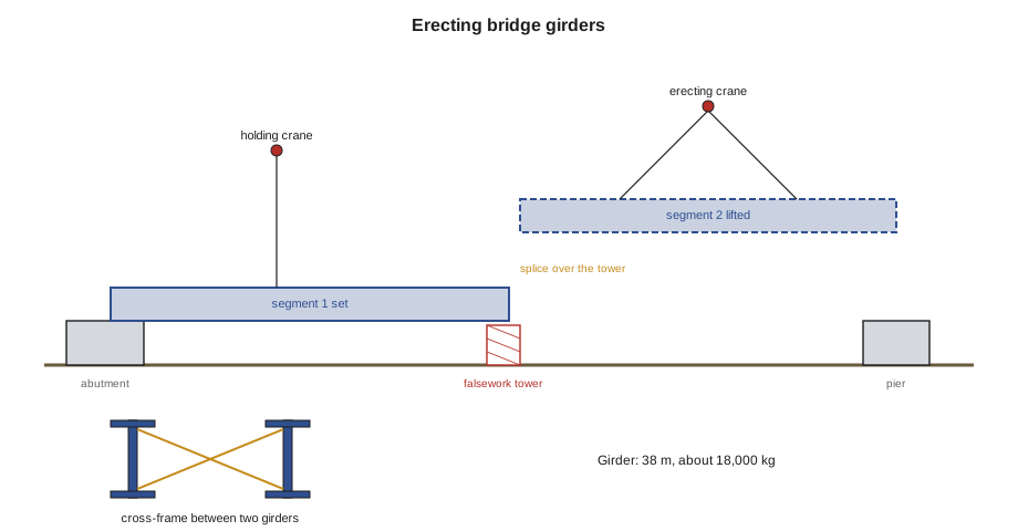
- Long girders may be spliced in the air over temporary supports, called falsework towers or shoring towers, because they are too long or heavy to lift in one piece.
Falsework and holding cranes
Falsework towers are temporary supports designed by an engineer, set on foundations or mats, and checked by survey. A girder segment resting on a falsework tower is held there while the next segment is spliced to it. The tower must carry the girder's weight, the splice crew and equipment, and the wind, and it must not settle. Falsework also carries the girders until enough of the span is connected to stand on its permanent bearings.
A holding crane is a crane that keeps a load on a girder already set, taking part of its weight and holding it steady while the next piece is connected. The holding crane's lift plan says how much load it holds and for how long, and it must never be released until the procedure's conditions are met.
Tandem lifts
Many bridge girders are lifted by two cranes, one at each end, because one crane would need to be enormous to reach the middle of the span with the whole girder. A tandem lift is always a critical lift. Each crane carries part of the load, which depends on where the girder's centre of gravity is between the pick points, and the share can change as the girder moves, tilts or as one crane boom moves faster than the other. Lift plans for tandem lifts commonly limit each crane to about 75 in 100 of its chart, to leave room for that shifting load, and one lift director gives all the signals.
Worked problem
Load shares on a tandem lift
Each footbridge girder weighed 18,000 kg, and the rigging added 600 kg, for 18,600 kg in all. The pick points were 2 m in from each end of the 38 m girder, so 34 m apart. Because of a heavier stiffened end, the centre of gravity was 1.0 m off the middle, toward crane B. What load did each crane carry, and what chart capacity did crane B need under a 75 in 100 rule?
Show solution
- Distance from pick A to the centre of gravity = 17 + 1.0 = 18.0 m.
- \[R_B = \frac{W \times 18.0}{34} = \frac{18{,}600 \times 18.0}{34} \approx 9{,}847\ \text{kg}\]
- R_A = 18,600 − 9,847 = 8,753 kg.
- Crane B needs a chart value of at least 9,847 ÷ 0.75 ≈ 13,130 kg at its radius.
Answer: Crane B carried about 9,850 kg (21,760 lb) and crane A about 8,750 kg (19,540 lb). If the plan had assumed an even split, crane B would have been loaded more than planned. The fabricator's weight and centre of gravity, stated on the shop drawing, were used, not an estimate.
Cross-frames and diaphragms
Cross-frames are small trusses, usually of angles in an X or K shape, between girders. Diaphragms are solid members such as channels or beams. They hold the girders upright during erection and the deck pour, and on curved and skewed bridges they share load between girders. Their connections are often designed so that the girders can be adjusted into line before final bolting, and on curved or skewed bridges the order of installing them, and whether the girders are held at a particular shape while bolting, is set by the engineer's erection procedure.
On the rail footbridge, the plan was to set girder 1, hold it with crane A while crane B set girder 2 beside it, then bolt four cross-frames with half their bolts before either crane let go, then finish the bolts. The crew had the cross-frames rigged on the abutment, the bolts bagged by frame, and two aerial lifts on the abutments for the end frames.
Working over rail, traffic and water
Work over a railway is done under the railway's rules: a track possession or work block, a railway flag person or protection supervisor, minimum clearances to the track and overhead electrical lines, and insurance and training required by the railway. Nobody goes near the tracks without the railway's protection in place. On the footbridge job, the possession ran from 12:50 a.m. to 4:50 a.m. on a Sunday in September 2023, and the railway's protection supervisor gave the start and the end of the block.
Over a highway, the road is closed or traffic is diverted under the road authority's traffic control plan, usually at night, and no load is carried over live traffic. Over water, the plan covers rescue boats, life jackets or work positioning as required, and the risk of dropping tools into the water.
The footbridge girders were set with 70 minutes to spare. Carla's memory of the night was not the cranes but the cross-frames: one had been fabricated with a hole pattern for the wrong side, and the crew had to swap it with its mirror image, which had been loaded at the bottom of the bundle. "Load the trailer in the order you'll use it," she said. "Night work punishes every small mistake."
Bearings and the deck pour
Bridge bearings, whether elastomeric pads, pot bearings or sliding bearings, are set to line, level and position by survey before the girders land, and some are set with offsets for the temperature at the time, so that they are centred at the average temperature. The ironworkers set the girders on them without disturbing them, and anchor bolts and keeper plates are installed as the drawings show. Before the deck is poured, the girders' elevations are surveyed, the deck formwork and overhang brackets are installed, often by ironworkers, and the cross-frames are checked complete, because the wet concrete is the heaviest load the girders carry before the deck hardens.
Bridges and the ironworker
Bridge work combines most of this course: heavy picks, tandem lifts, long-member stability, temporary works, survey, night work and work over the public. It also includes rebar for the deck, which is IRW-220's subject, and often shear studs, IRW-230's. Many ironworkers spend whole careers on bridges. The habits are the same as on buildings, but the margins are smaller: there is less room on a bridge, less time in a possession, and less forgiveness for a dropped bolt over a highway.
Planning a night in a possession
A short rail or road window is planned like a shutdown, to the minute. For the footbridge, the plan had a timeline on one sheet: cranes set up and outriggers on mats before the window, rigging attached and inspected, the lift director's briefing at 12:30 a.m., the railway's start of protection at 12:50, the first girder in the air at 1:05, girder 2 at 1:50, cross-frames with half their bolts by 3:10, cranes released by 3:40, tracks cleared and inspected by 4:20 and protection handed back by 4:50. Each step had a person responsible and a decision point: if the first girder was not set by 2:15, the second would not be lifted that night, and the plan said how girder 1 would be secured on its own.
The crew rehearsed the sequence the afternoon before on the ground, with the cranes rigged but not lifting, so that everyone knew where to stand and what to do. Tools and bolts for each step were in labelled bins at each abutment, and two spare cross-frames and a box of extra bolts were on the truck in case anything was damaged or wrong.
Deck overhangs and formwork
Bridge decks usually overhang the outside girders, and the overhang forms are carried on brackets attached to the girders. The brackets push sideways on the girder webs and bottom flanges and can twist the outside girder while the deck concrete is wet. The erection or deck-forming engineer designs the brackets, their spacing and any temporary ties or struts between girders to resist this. Ironworkers who install the brackets must place them at the spacing shown, never weld them to the girders unless the drawings allow it, and make sure the temporary ties are tight before the pour.
Inspection before the pour
Before the deck is poured, the owner's inspector checks the girder elevations against the planned profile, the cross-frame bolting, the bearings and their keepers, the shear studs, the overhang brackets and the deck reinforcement. Any temporary works, such as falsework towers, that are to stay until after the pour are checked again. After the pour, the girders deflect under the concrete as designed, and the final survey records the shape of the finished deck.
Curved and skewed girders
Curved girders are heavier on their outside and want to rotate, and skewed bridges, where the supports are not square to the girders, have girders whose ends sit at different stations. Both need careful erection engineering: curved girders are often erected in pairs, braced together on the ground and lifted as a unit, and skewed girders may be held at a particular shape while their cross-frames are bolted so that the finished bridge comes out right. The engineer's procedure says which cross-frames are bolted first, which are left loose until the deck is poured, and how the girders are to be held. The crew follows the order exactly, because the wrong order can lock the girders into the wrong shape.
Girder ends at skewed bearings also need care in landing: the end sits on its bearing at an angle, and its anchor bolts and keepers must line up. Survey of the girders before and after landing is part of the plan.
Common mistakes
MistakeReleasing a single girder before it is braced.
InsteadHold the first girder until the second is set and cross-frames are bolted as the procedure says.
MistakeAssuming the load splits evenly on a tandem lift.
InsteadUse the actual centre of gravity to find each crane's share.
MistakeGoing near the tracks before the railway's protection is in place.
InsteadWait for the protection supervisor or flagger to start the block.
MistakeLoading a trailer in any order for a night job.
InsteadLoad in the order of use, with every part checked.
MistakeDisturbing bearings when landing girders.
InsteadSet girders gently on surveyed bearings and install keepers as shown.
Summary and key terms
- Steel bridges use rolled beams, plate girders or box girders on bearings, braced by cross-frames or diaphragms.
- Bridges follow CSA S6 and the owner's specifications, with sealed erection procedures.
- Girders are unstable until braced; the first girder is held until the second is set and cross-frames are bolted.
- Falsework towers and holding cranes support girders during splicing and setting.
- Tandem lifts are critical lifts; each crane's share depends on the centre of gravity, and charts are commonly limited to about 75 in 100.
- Work over rail, traffic and water follows the owner's protection rules and tight time windows.
- Plate girder
- A deep girder made by welding plates into an I shape.
- Cross-frame
- A small truss between girders that braces them.
- Falsework tower
- A temporary tower that supports girders during erection.
- Holding crane
- A crane that holds part of a girder's weight while the next piece is connected.
- Tandem lift
- A lift made with two cranes sharing one load.
- Work window
- A period when the railway stops trains so that work can be done near the tracks; also called a track possession or work block.
Practice problems
Work each problem on paper first, then reveal the answer to check.
A 20,000 kg girder is lifted at two points 30 m apart with its centre of gravity at mid-length. What does each crane carry?
Show answer
10,000 kg each.
If the centre of gravity is 1.5 m toward crane B, what does B carry?
Show answer
20,000 × 16.5 ÷ 30 = 11,000 kg.
Under a 75 in 100 rule, what chart capacity does B need?
Show answer
11,000 ÷ 0.75 ≈ 14,667 kg.
What holds the first girder until the second is set?
Show answer
The crane, a holding crane, temporary bracing or falsework, as the procedure says.
Who starts a work block near the tracks?
Show answer
The railway's protection supervisor.
Lesson quiz · 5 questions
Score 60% or more to complete this lesson.
Create a free account to save your progress, take quizzes and earn a certificate.