
INS-320 · Lesson 12 of 12 · 27 min
Case study: an ice rink refrigeration plant
▶ Video coming soon A video version of this lesson is on the way.
Carrow Park Arena is a single-pad community arena that the city has run since 1976. By 2025 its refrigeration plant was near the end of its life: the original brine chiller was leaking, the brine headers in the trench at the end of the rink were badly corroded under their old insulation, and the plant's controls were obsolete. The city hired a refrigeration contractor, Frostline Refrigeration, to renew the plant during the summer of 2026, when the ice was out, so that the rink could open on time in August for summer hockey schools. The rink floor itself, with its grid of floor pipes in the concrete slab, was sound and stayed. Coldstream was hired, through Frostline, to insulate the new cold equipment and piping. Raj Sandhu estimated the job, Marcel Ouellet led it, Tessa Moreau was his partner for the three weeks, and Bernie Valois inspected. This lesson follows the job from the walk-down to the infrared check after start-up, and uses it to bring together the methods of the whole course.
How the arena plant works
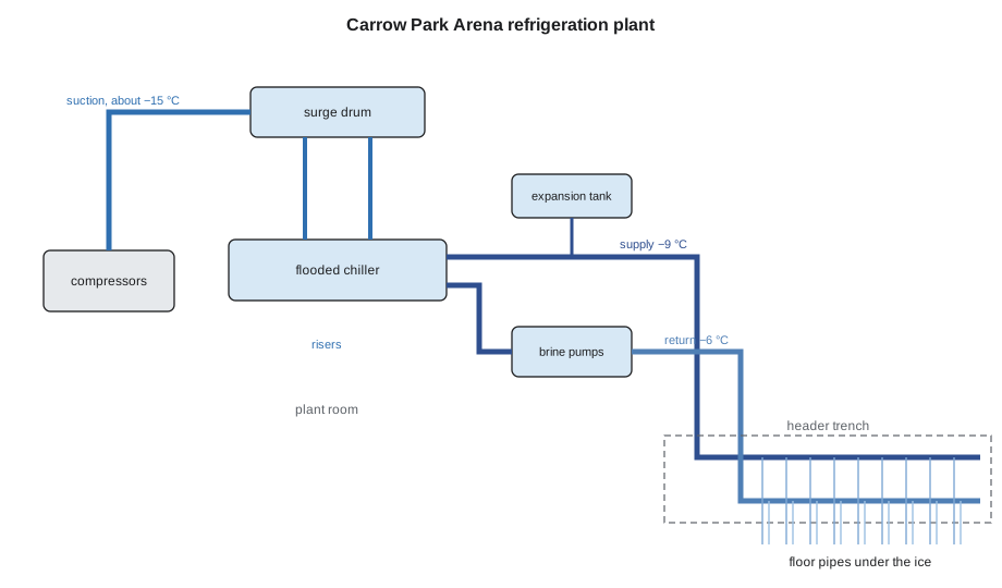
The arena uses an indirect system, which is common in rinks. A small ammonia plant in the refrigeration room chills a secondary coolant, calcium chloride brine, and pumps carry the brine out through headers to the floor pipes, where it freezes the ice, and back again. Only brine, not ammonia, goes under the ice, so the ammonia stays in the plant room with its detection and ventilation.
- Ammonia side. Compressors draw cold ammonia vapour from a surge drum, a vessel above the chiller that separates vapour from liquid. Liquid ammonia flows from the surge drum down into the shell of a flooded chiller, a shell-and-tube heat exchanger, where it boils at about −15 °C (5 °F) around the tubes, and the vapour rises back to the surge drum. The compressors send hot gas to an evaporative condenser on the roof, and the condensed liquid returns through a receiver and a control valve to the surge drum.
- Brine side. Two brine pumps (one running, one standby) push brine through the chiller's tubes, where it is cooled to about −9 °C (16 °F), then through the supply header to the floor. The brine returns at about −6 °C (21 °F) through the return header. The headers run through the plant room and then along a header trench, a covered concrete channel under the rink's end boards, where the floor pipes connect to them. A small expansion tank allows for the brine's volume changes.
The temperatures are typical for a recreational rink; the plant's controls vary them with the ice conditions. Under the rink slab, a layer of insulation board and a heated sub-floor keep the ground below from freezing, as lesson 7 described for freezers.
The ammonia charge is small for an industrial plant, about 450 kg, but the same rules apply as at Kellerton. The plant is registered with the TSSA and is operated under Ontario's rules for refrigeration plants and operators, and its design follows CSA B52. Coldstream's crew did Frostline's site orientation, worked under its permits once the ammonia side was charged, and followed the plant room's detection and entry rules.
The scope and specification
The city's consulting engineer had written the insulation specification. Coldstream's scope was the new cold equipment and piping, but not the floor pipes, which are in the slab, nor an older brine return branch in the ice resurfacer room, which stayed as it was. The specification called for:
- Ammonia suction line (NPS 5, 14 m (46 ft) from the surge drum to the compressors), ammonia risers between surge drum and chiller (NPS 4, 8 m (26 ft) in all), the chiller shell and heads and the surge drum: cellular glass in two layers of 38 mm (1 1/2 in), 76 mm (3 in) in all, joints staggered and sealed with joint sealant, two coats of vapour retarder mastic with fabric, aluminum jacket with factory moisture barrier and stainless bands, no screws; contraction joints in each layer within about 600 mm (2 ft) of each elbow on the suction line; labels to IIAR guidance.
- Brine headers in the plant room (two NPS 8, 12 m (39 1/2 ft) each): PIR 51 mm (2 in) with a factory vapour retarder jacket to ASTM C1136, sealed laps and butt strips, a PVC jacket of 0.5 mm (20 mil), and high-density inserts at all supports.
- Brine headers in the header trench (two NPS 8, 26 m (85 ft) each): as first issued, cellular glass 51 mm (2 in), two coats of reinforced mastic and a PVC jacket of 0.76 mm (30 mil), because the trench is wet when the ice is removed or the floor is washed; contraction joints at about 9 m (30 ft) and near the elbows at each end.
- Brine pumps: removable, sealed covers lined with two layers of 25 mm (1 in) elastomeric, stopping short of motors and couplings. Expansion tank: elastomeric and PVC.
- Throughout: vapour stops at both sides of every valve and flange, at every support insert and at no more than 3 m (10 ft) on straight runs; design conditions of 30 °C and 50 in 100 RH (86 °F and 50 in 100 RH) in the plant room and 20 °C and 85 in 100 RH (68 °F and 85 in 100 RH) in the trench; surfaces to stay at least 2 °C (4 °F) above the design dew point.
The estimate
Raj estimated the job from the drawings using Coldstream's own labour units, which come from the company's records of similar work. The table shows the estimate as revised after the change to the trench described below. The labour units are company figures, not industry standards.
| Item | Quantity | Labour unit | Hours |
|---|---|---|---|
| NPS 5 ammonia suction, 2 layers cellular glass | 14 m | 1.6 h/m | 22.4 |
| NPS 4 ammonia risers | 8 m | 1.4 h/m | 11.2 |
| Chiller and surge drum (insulated surface) | 13.3 m² | 2.5 h/m² | 33.3 |
| NPS 8 brine headers, plant room, PIR | 24 m | 0.9 h/m | 21.6 |
| NPS 8 brine headers, trench, 2 layers cellular glass | 52 m | 1.4 h/m | 72.8 |
| Ammonia elbows and fittings | 10 | 1.5 h each | 15.0 |
| Brine elbows and fittings | 16 | 1.0 h each | 16.0 |
| NPS 8 valves, plant room | 8 | 2.0 h each | 16.0 |
| NPS 8 valves, trench | 4 | 2.5 h each | 10.0 |
| Brine pump covers | 2 | 6.0 h each | 12.0 |
| Expansion tank | 1 | 4.0 h | 4.0 |
| Labels, records and inspections | 1 | 6.0 h | 6.0 |
| Total | 240.3 |
The vessel area came from the insulated outside diameters. The chiller, 610 mm (24 in) across and 3.05 m (10 ft) long, measures 762 mm (30 in) over 76 mm (3 in) of insulation, giving a shell of π × 0.762 × 3.05 = 7.30 m² (2.5 × 10 = 78.5 ft²) and two 2:1 heads of about 1.084 × D² each, 1.26 m² (13.6 ft²) together. The surge drum, 508 mm (20 in) across and 1.83 m (6 ft) long, adds 4.74 m² (51.0 ft²). At about 240 hours, the job fitted two people for three weeks of five eight-hour days.
Week one: the walk-down and two problems
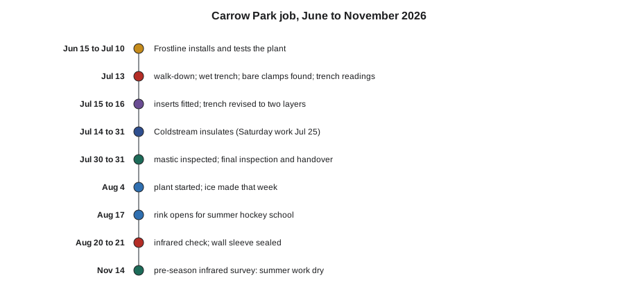
Frostline had installed the new equipment and piping from June 15 to July 10, pressure-tested both sides and released them for insulation. On Monday, July 13, Marcel and Tessa walked the plant with Frostline's lead mechanic, Nadia Ferrante, and the city's facility supervisor, Glen Kasprzak.
The first surprise was in the trench. Rain the week before, and water drained from the old headers, had left about 50 mm (2 in) of standing water along its length. The crew pumped it out, set up fans and a dehumidifier, and moved to the plant room for the day while the trench dried. The water was itself a warning: that trench would be wet again whenever the floor was washed or the ice melted.
The second problem was at the supports. On the ammonia suction line, Frostline had used factory cold shoes with high-density inserts. But three of the six supports on the plant-room brine headers had plain clamps bolted straight onto the steel. Marcel stopped work on the headers and sent a request for information through Raj. Frostline's crew jacked the headers at the three supports on Wednesday morning, fitted high-density inserts and shields of the right length, and reset the clamps around the shields, as lesson 10 describes.
On the Monday afternoon, Marcel took readings in the trench, which by then was dry underfoot but still damp: 21 °C and 88 in 100 RH, a dew point of about 18.9 °C. He checked the trench insulation against it and against the design conditions.
Worked problem
Is 51 mm enough in the trench?
The trench headers are NPS 8 (outside radius 109.55 mm) at −9 °C. Using the cylinder method of lesson 6, with cellular glass at a mean-temperature conductivity of about 0.036 W/m·K and a surface film coefficient of 8 W/m²·K, the surface temperatures work out as follows: with 51 mm, 18.0 °C in 20 °C air and 19.0 °C in 21 °C air; with 76 mm, 18.7 °C in 20 °C air and 19.7 °C in 21 °C air. Compare each with the dew point at the measured condition (21 °C, 88 in 100, dew point 18.9 °C), at the design condition (20 °C, 85 in 100, dew point 17.4 °C) and at 20 °C with 80 in 100 (dew point 16.4 °C). The specification requires a 2 °C margin.
Show solution
- Measured condition: 51 mm gives 19.0 − 18.9 = 0.1 °C; 76 mm gives 19.7 − 18.9 = 0.8 °C. Neither meets the margin, and 51 mm would sweat on such a day.
- Design condition: 51 mm gives 18.0 − 17.4 = 0.6 °C; 76 mm gives 18.7 − 17.4 = 1.3 °C. Neither meets 2 °C.
- At 80 in 100: 51 mm gives 18.0 − 16.4 = 1.6 °C, still short; 76 mm gives 18.7 − 16.4 = 2.3 °C, which meets the margin.
Answer: 51 mm could not keep the trench headers dry at the design humidity. 76 mm would, but only if the trench air were kept to about 80 in 100 RH.
Marcel sent the readings and his check to Raj, who passed them to the engineer. On Thursday, July 16, the engineer revised the trench insulation to two 38 mm (1 1/2 in) layers of cellular glass and asked the city to add a small exhaust fan to the trench cover to keep its air closer to the room's, which the city's electrician installed the following week. Raj priced the extra layer as a change: the trench labour unit rose from 1.13 to 1.4 hours per metre (0.345 to 0.43 hours per foot), about 14 hours in all. The second layer added mastic too: lesson 5's calculation for this trench, at the revised thickness, gave 8 pails.
Weeks two and three: the work
Tessa started the ammonia suction line on Tuesday, July 14, with the inner layer of cellular glass, fitting each section to the pipe, buttering every joint with sealant, and turning the second layer's joints a quarter turn from the first and staggering its butt joints by half a section. Marcel built the contraction joints near each elbow, with packed gaps offset between the layers, and the vapour stops at each valve and flange.
Worked problem
How much do the lines move?
The suction line is installed at about 25 °C and runs at about −15 °C; the trench headers are installed at about 20 °C and run at about −9 °C. Using 11.7 millionths per °C for steel, how much does the 14 m suction line shorten, and each 26 m trench header?
Show solution
- Suction: 14,000 × 0.0000117 × 40 = 6.6 mm.
- Trench header: 26,000 × 0.0000117 × 29 = 8.8 mm.
- With joints at about 9 m and near each end, each joint takes a few millimetres.
Answer: About 7 mm on the suction line and 9 mm on each trench header, small but enough to crack rigid insulation fixed at both ends.
In the second week, Marcel and Tessa insulated the chiller and surge drum with curved cellular glass segments and head gores, the risers and the plant-room brine headers. The PIR for the plant room arrived on Monday, July 20, and on receiving it Tessa found that one carton of NPS 8 sections had come without the factory vapour retarder jacket; it went back, and the replacements arrived on Wednesday. On Saturday, July 25, the two of them worked an extra day in the trench to keep to the schedule, starting the inner layer of the headers now that the trench was dry and its new fan was running.
The third week went to the trench: the second layer of cellular glass, the two coats of mastic with fabric, the wet film readings on every section, Bernie's inspection of the coated headers on Thursday, July 30, before the PVC jacket went on, and the pump covers, the expansion tank and the valve covers. One of the trench's NPS 8 butterfly valves had been installed with its gear operator facing the trench wall, leaving no room for the planned cover box; Marcel rebuilt the box as a two-piece cover that opened from the top, which cost about three hours. The crew labelled every ammonia line on its new jacket in the places Nadia had marked, with the service, the pressure level and the flow direction, and labelled the brine headers.
Inspection and handover
On Friday, July 31, Bernie, Nadia and Glen walked the job. They found three items: a band on the suction line jacket that was tight against a lap and had begun to cut the moisture barrier, an unsealed edge where a pump cover met the pipe insulation, and a label covered by a cover box. All three were fixed that afternoon. Marcel handed Glen the job record: a marked drawing showing every vapour stop, contraction joint and the four inspection plugs the city had asked for at low points in the trench, the material data sheets, the wet film readings, photographs of the vapour retarder before jacketing, and a note on the pump and valve covers: "Cold service. Reseal after every opening."
The crew's actual hours were 252, against the revised estimate of 240. The trench water on the first Monday cost about six hours, the jacketless PIR carton about three and the valve box rebuild about three. Raj recorded each cause on the job's closing sheet for the next estimate. Frostline started the plant on Tuesday, August 4, pulled the floor down, painted and flooded the ice that week, and the rink opened for summer hockey school on Monday, August 17.
After start-up
On Thursday, August 20, with the plant running at its normal temperatures, Marcel came back with an infrared camera. Every header, the chiller and the suction line showed even surface temperatures, just below the room's, except one spot: where the supply header passed from the plant room into the trench through a sleeve in the trench's end wall, a ring of the jacket was a few degrees colder than the rest. Marcel opened it the next day and found that the vapour retarder mastic had not been carried into the sleeve on the plant-room side; air was moving through the sleeve along the insulation. He sealed the sleeve, carried the coating through and added a vapour stop at the wall face, as lesson 7 describes for freezer walls. In November, when he and Tessa surveyed the plant again before the winter season (lesson 11), the summer work was dry throughout.
What the job shows
Marcel used the Carrow Park job to close the fall sessions on November 9. He asked the apprentices to find the course in it:
- Cold is different (lesson 1): every decision on the job was about keeping water out, not heat in.
- Dew point (lesson 2): measuring the trench, not just reading the specification, caught a design that would have sweated.
- Vapour drive (lesson 3): the one unsealed sleeve showed how air leakage finds the single gap.
- Materials (lesson 4): cellular glass where it gets wet, PIR in the dry plant room, elastomeric on the pumps.
- Vapour retarders (lesson 5): reinforced mastic at the specified wet film, inspected before the jacket covered it.
- Refrigeration piping (lesson 6): labels, valves left usable, and the plant's ammonia rules followed.
- Contraction (lesson 9): packed joints near elbows and along the headers.
- Supports (lesson 10): three bare clamps stopped and fixed before insulating, not after.
- Inspection (lesson 11): the infrared check after start-up found the sleeve leak while it was cheap to fix.
"Nobody will ever notice that trench," Marcel said. "That's the point. If we did it right, in twenty years somebody will open an inspection plug and find dry insulation, and they'll never know our names."
Common mistakes
MistakeInsulating a humid trench to the specified thickness without checking the conditions.
InsteadMeasure the conditions at the work, check the dew point margin, and raise it before installing.
MistakeInsulating over supports with clamps on the pipe.
InsteadStop and have the pipefitters fit inserts and shields first.
MistakeAccepting a delivery without checking the vapour retarder jacket.
InsteadCheck every carton against the specification when it arrives.
MistakeCovering mastic with the jacket before it is inspected.
InsteadHold the jacket until the foreperson or inspector has seen the vapour retarder.
MistakeTreating the job as finished at handover.
InsteadCheck it with infrared once the system is running and fix what shows.
Summary and key terms
- The arena uses ammonia to chill calcium chloride brine, which is pumped through headers in the plant room and trench to the floor pipes.
- The specification set materials by location: cellular glass on ammonia and in the wet trench, PIR in the dry plant room, elastomeric on pump covers, all with vapour stops and sealed retarders.
- Measuring the trench showed the design thickness could not meet the dew point margin; the engineer added a layer and ventilation.
- Missing inserts on three supports were found and fixed before insulating.
- Contraction joints, sealed joints, reinforced mastic at the right film thickness and inspection before jacketing were built into the work.
- The estimate was revised for the change, and actual hours were recorded against it with the causes of the overrun.
- An infrared check after start-up found one unsealed wall sleeve, fixed the next day; the November survey found the summer work dry.
- Indirect system
- A refrigeration system in which the refrigerant chills a secondary coolant that is pumped to the load.
- Secondary coolant
- A fluid, such as brine or glycol, that carries cold from a refrigeration plant to where it is used.
- Brine
- A solution of a salt, such as calcium chloride, in water, used as a secondary coolant below freezing.
- Surge drum
- A vessel above a flooded chiller that separates refrigerant vapour from liquid.
- Flooded chiller
- A shell-and-tube heat exchanger whose shell is kept full of boiling refrigerant around tubes carrying the coolant.
- Header trench
- A covered channel at the end of a rink where the floor pipes connect to the supply and return headers.
- Change order
- An agreed change to the scope and price of a contract.
Practice problems
Work each problem on paper first, then reveal the answer to check.
Why does the arena use brine under the ice instead of ammonia?
Show answer
So the ammonia stays in the plant room, with its detection and ventilation, and only brine goes under the ice.
Why was cellular glass chosen for the trench headers?
Show answer
The trench gets wet; cellular glass does not take up water and is impermeable.
The trench at 21 °C and 88 in 100 RH has a dew point of 18.9 °C. With 76 mm the surface is 19.7 °C. What is the margin?
Show answer
0.8 °C, less than the 2 °C required.
What three causes did Raj record for the 12-hour overrun?
Show answer
The trench water, the carton of PIR without its jacket and the valve box rebuild.
What did the infrared check on August 20 find?
Show answer
A cold ring at the wall sleeve where the vapour retarder had not been carried through and sealed.
Lesson quiz · 5 questions
Score 60% or more to complete this lesson.
Create a free account to save your progress, take quizzes and earn a certificate.