
INS-320 · Lesson 10 of 12 · 21 min
Supports and hangers on cold lines
▶ Video coming soon A video version of this lesson is on the way.
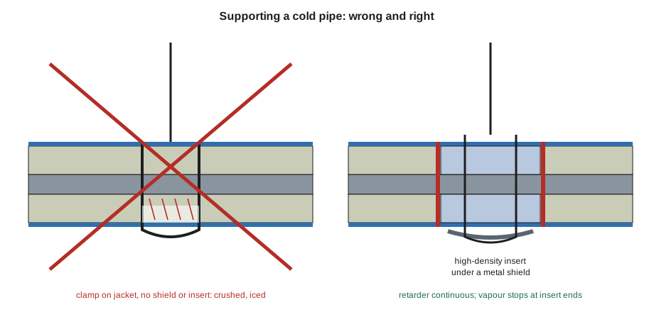
At the November 9 session, the week after the Kellerton outage, Devon put a cardboard box on the table and lifted out what was left of the hanger section from the iced suction line: two curved pieces of cellular glass, cracked straight through where a clevis hanger had clamped round the outside of the jacket, and a section of jacket with the band still on it. He had photographs on his phone of the hanger before they cut it away: the clevis bolted tight around the jacket, with no shield and no insert, crushing the insulation onto the pipe. "That's where four years of ice came from," Marcel said. "One support done wrong. The rest of that line was fine."
Supports are where cold systems fail most often. A pipe must be held up, guided and anchored by steel that is attached to the building, and wherever the steel meets the pipe, it carries cold out of the pipe and loads the insulation. This lesson covers why supports cause trouble on cold lines, how load-bearing inserts and shields solve it, how to check that an insert can carry the load, and how supports, anchors, guides and risers are detailed so that the vapour retarder stays continuous.
Why supports are the weak point
On a hot line, a clamp directly on the pipe costs some heat, which is why hot lines often use clamps on the pipe with insulation built around them. On a cold line, the same clamp causes three problems at once.
- A thermal bridge. Steel conducts heat hundreds of times better than insulation. A clamp, rod or shoe touching the cold pipe becomes as cold as the pipe, carries heat in from the building, and is cold enough to sweat or frost along its length.
- A break in the vapour retarder. Insulation cannot be sealed tightly around a clamp and its bolts, so humid air reaches the pipe at every support.
- A crushing load. If the clamp goes outside the insulation instead, without a shield and a load-bearing insert, the weight of the pipe is carried on a narrow band of insulation that was never meant to carry it. The insulation crushes, cracks, and the jacket and vapour retarder split, exactly as on the Kellerton line.
The cure for all three is the same: support the cold pipe through a load-bearing insert that is part of the insulation, cover the insert with a shield that spreads the load from the hanger, and keep the vapour retarder continuous over both.
Inserts and shields
A load-bearing insert is a section of insulation, the same thickness as the pipe insulation, made of a material strong enough to carry the pipe's weight at the support. Common types are:
- High-density rigid foam inserts, of polyisocyanurate or polyurethane made much denser than ordinary pipe insulation, typically several times as dense, with much higher compressive strength. They are the most common inserts on chilled water and refrigeration lines and are often supplied with a factory vapour retarder jacket and sometimes with a bonded shield.
- Cellular glass inserts, sometimes of a higher-strength grade, used where the line is insulated with cellular glass, with the shield spreading the load.
- Hardwood blocks, an older method still seen on existing systems. Wood conducts more heat than foam, and if it gets wet it rots and swells, so most current cold specifications call for foam or cellular glass inserts instead.
Materials that wick water, such as calcium silicate and fibrous inserts, are not used on cold service.
A shield is a curved sheet metal plate fitted around the outside of the insulation at the support, under the hanger, clamp or saddle. It spreads the hanger's load over the insert. Shields are made in standard lengths and gauges for each pipe and insulation size; INS-130 introduced the MSS SP-58 type usually used, and the Mountview shields of 300 to 600 mm (12 to 24 in) with their bonded inserts. The insert should be at least as long as the shield, so the shield never bears on ordinary insulation, and the shield must not have sharp edges that cut the vapour retarder.
Will the insert carry the load?
Inserts are chosen from the maker's tables for the pipe size, load and support spacing, but a simple check shows why they work and why a hanger on ordinary insulation does not. The load at each support is the weight per metre or foot of everything carried, times the support spacing. A common simple check takes the bearing area as the insert length times the pipe's outside diameter, the area of the pipe's shadow on the insert, and compares the bearing pressure with the material's compressive strength divided by a safety factor.
Worked problem
Checking the Kellerton suction line support
The NPS 4 suction line (outside diameter 114.3 mm, inside diameter 102.3 mm) weighs 16.07 kg/m as bare steel. To be safe, assume it could be full of liquid ammonia (690 kg/m³) during a plant upset. Its 51 mm of cellular glass (117 kg/m³) and jacket add about 3.1 and 1.5 kg/m. Supports are 3.0 m apart and the insert is 300 mm long. Cellular glass has a compressive strength of about 620 kPa; use a safety factor of 4. Is the insert pressure acceptable? What if a clamp bore on a strip of insulation only 50 mm by 20 mm instead?
Show solution
- Ammonia: π ÷ 4 × 0.1023² × 690 = 0.008219 × 690 = 5.67 kg/m.
- Total weight = 16.07 + 5.67 + 3.1 + 1.5 = 26.34 kg/m.
- Load per support = 26.34 × 3.0 = 79.0 kg; force = 79.0 × 9.81 = 775 N.
- Bearing area = 0.300 × 0.1143 = 0.0343 m²; pressure = 775 ÷ 0.0343 = 22,600 Pa = 22.6 kPa.
- Allowable = 620 ÷ 4 = 155 kPa. 22.6 kPa is well within it.
- Clamp on a 0.050 × 0.020 = 0.001 m² strip: pressure = 775 ÷ 0.001 = 775 kPa, five times the allowable and more than the material's crushing strength.
Answer: The insert sees about 23 kPa, far below the 155 kPa allowed; the same load on a clamp's narrow contact strip would be about 775 kPa and crush the insulation.
The figures are typical for illustration; insert makers publish tested load ratings for each insert, shield and pipe size, and those govern. The check also explains why shields matter even with strong inserts: a hanger rod's clevis without a shield touches the insulation along a line, not an area, and concentrates the load just as the clamp did.
Types of support on cold lines
Each type of support has its own cold detail. The engineer's or maker's details govern; these are the common arrangements.
- Clevis and band hangers on rods carry the pipe from above. On cold lines the hanger goes around the shield, which sits over the insert. The rod never touches the pipe.
- Trapeze supports carry several pipes on a steel member. Each cold pipe rests on its own shield and insert, often with a cradle or saddle to stop it rolling.
- Pipe shoes are steel cradles that sit on beams or racks and let the pipe slide. A shoe welded to a cold pipe is a large thermal bridge, so cold lines use cold shoes: factory assemblies with a high-density insert clamped between the pipe and a steel cradle, so the steel never touches the pipe.
- U-bolts and pipe clamps on racks are only used on cold lines over a shield and insert, never tightened onto the insulation or the pipe through it.
- Guides keep the pipe in line while it slides. The guide bears on the shield or cold shoe, not on the pipe, and the shield must be long enough to stay on the guide over the full movement (lesson 9).
- Anchors hold the pipe fixed. Some are designed as insulated anchor assemblies with load-bearing inserts. Where an anchor is steel welded to the pipe, the steel is insulated for a distance from the pipe, commonly about four times the insulation thickness, with its own vapour retarder sealed to the pipe insulation's.
- Riser clamps carry vertical pipe. On cold risers, the clamp grips a shield over a high-density insert collar, so the pipe's weight is carried through the insert, not by a steel clamp on the bare pipe.
Keeping the vapour retarder continuous
At every support, the vapour retarder of the pipe insulation must carry on over the insert without a break.
- The insert's own factory jacket, or the vapour retarder mastic, is lapped and sealed onto the pipe insulation's vapour retarder on both sides.
- The joints between the insert and the pipe insulation are sealed like any other joint, and many specifications place a vapour stop at each end of the insert, so the support area is a sealed section of its own.
- The shield goes over the vapour retarder and does not pierce it. Shields are held by bands or by the hanger, never by screws through the retarder.
- Hanger rods, guide lugs, anchor steel and any attachment that comes close to or through the insulation are insulated and sealed where they pass, with the seal carried along them for a distance.
On jacketed lines, the jacket goes over the shield or stops at it and is sealed at the edge, as the specification shows; the shield is never buried under the insulation where nobody can see whether it is crushing.
Coordinating with the pipefitters
Inserts have to be in place when the pipe is hung, because a pipe resting on its hanger cannot have an insert slipped under it without being lifted. On new work, that means the insulation contractor and the pipefitters agree before the pipe goes up who supplies and installs inserts and shields, at what size and length, and when. On many jobs the pipefitters install inserts and shields supplied by the insulator; on others the insulator supplies and installs them as the pipe is hung. At Mountview, Harcourt installed shields with bonded inserts on the chilled water and heating mains as the pipe went in.
When supports are found without inserts, the fix belongs to the pipefitters or the plant's mechanics: the pipe must be jacked or lifted at the support, the insert and shield fitted, and the hanger reset, with the line's owner agreeing to the work. On the Kellerton line, the pipefitters fitted the insert and shield during the outage while Marcel and Devon worked on the insulation each side. On the arena job in July, Marcel found three plant-room supports on the new brine headers with clamps straight on the pipe; he stopped, sent a request for information through Raj, and the refrigeration contractor's crew lifted the headers and fitted inserts before the insulation went on, as lesson 12 describes. The insulator's job is to find the problem before covering it, not after.
Inspecting supports
Supports deserve the closest look on any cold system inspection, new or old. Check that:
- Every support has a shield and insert of the right size, and the insert is at least as long as the shield.
- No hanger, clamp or U-bolt bears on ordinary insulation or crushes the jacket.
- Shields are centred on their supports and on guides have enough length for the pipe's movement.
- The vapour retarder is continuous and sealed at both ends of every insert, with vapour stops where specified.
- Anchors, lugs and rods near the pipe are insulated and sealed for the specified distance.
- There is no frost, sweating, rust staining or crushed jacket at any support, which are early signs of failure.
Common mistakes
MistakeClamping a cold pipe directly or tightening a clamp onto its insulation.
InsteadSupport it on a shield over a load-bearing insert.
MistakeUsing an insert shorter than the shield.
InsteadMake the insert at least as long as the shield so the shield never bears on ordinary insulation.
MistakeScrewing a shield on through the vapour retarder.
InsteadHold it with bands or the hanger; nothing pierces the retarder.
MistakeWelding a shoe to a cold pipe and insulating around it.
InsteadUse a cold shoe with a high-density insert, or insulate and seal the steel as the specification details.
MistakeInsulating over supports that have no inserts.
InsteadStop and report it; the pipe must be lifted and inserts fitted first.
Summary and key terms
- Supports are the most common failure point on cold lines: steel is a thermal bridge, breaks the vapour retarder and can crush insulation.
- Cold pipe is supported through a load-bearing insert under a metal shield, with the vapour retarder continuous over both.
- High-density foam and cellular glass inserts are common; wicking materials are not used, and wood is an older method.
- A simple check compares the load per support divided by the bearing area with the insert's strength divided by a safety factor; makers' ratings govern.
- Hangers, trapezes, cold shoes, guides, anchors and riser clamps each have a cold detail that keeps steel off the pipe.
- Inserts must be in place when the pipe is hung; missing inserts are fixed by lifting the pipe, not by insulating around them.
- Inspect every support for inserts, shields, sealing and early signs of failure.
- Thermal bridge
- A path of conductive material, such as steel, that carries heat across insulation.
- Load-bearing insert
- A section of strong insulation at a support that carries the pipe's weight.
- Shield
- A curved sheet metal plate around the insulation at a support that spreads the load.
- Cold shoe
- A pipe shoe assembly with a high-density insert so its steel does not touch a cold pipe.
- Riser clamp
- A clamp that supports the weight of a vertical pipe.
- Bearing pressure
- The load on a support divided by the area that carries it.
- Safety factor
- A number by which a material's strength is divided to give a safe working value.
Practice problems
Work each problem on paper first, then reveal the answer to check.
Why is a clamp directly on a cold pipe a problem even if the insulation is sealed around it?
Show answer
The clamp is a thermal bridge that sweats or frosts, and the seal around it cannot stay tight.
A support carries 900 N on a bearing area of 0.04 m². What is the pressure?
Show answer
900 ÷ 0.04 = 22,500 Pa = 22.5 kPa.
An insert material has a compressive strength of 1,000 kPa. With a safety factor of 4, what is the allowable pressure?
Show answer
1,000 ÷ 4 = 250 kPa.
Why should the insert be at least as long as the shield?
Show answer
So the shield's ends never bear on ordinary insulation.
You find three supports on a new cold line with no inserts. What do you do?
Show answer
Stop, report it, and have the pipefitters lift the pipe and fit inserts before insulating.
Lesson quiz · 5 questions
Score 60% or more to complete this lesson.
Create a free account to save your progress, take quizzes and earn a certificate.