
INS-210 · Lesson 7 of 12 · 24 min
Strainers, traps and specialties
▶ Video coming soon A video version of this lesson is on the way.
Every few metres along the Kellerton steam lines there was something that was not pipe, not a valve and not a flange: a Y-strainer with a blowdown valve on its cap, a drip leg with a trap hanging under it, a pressure gauge on a siphon, a thermometer in a well, a union, a sight glass. Devon asked Marcel whether they insulated all of it. "Some of it you must, some of it you mustn't, and some of it you do only halfway," Marcel said. "The trick is knowing which is which before you pick up the knife." He started Devon on a list in his notebook headed "things that have to breathe, things that have to be read, things that have to come apart."
Piping systems are full of specialties: devices that clean, drain, measure, vent, absorb movement or protect the system. Each one needs a decision about insulation. Some must be insulated for the same reasons as the pipe. Some must be left bare to work properly. Many must be insulated with a removable section so they can be read, cleaned or replaced. This lesson goes through the specialties insulators meet most often: strainers, steam traps, unions, expansion joints and flexible connectors, gauges and thermometers, test ports, air vents, drains and sight glasses, and the nameplates and tags that must stay readable.
Strainers
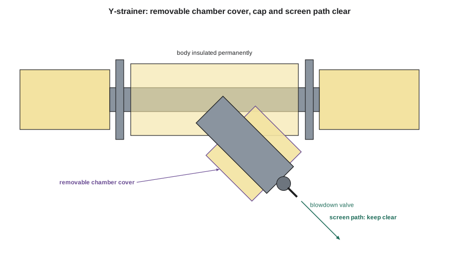
A strainer catches dirt, scale and weld slag before they reach a valve, a pump, a coil or a trap. The common Y-strainer has a body like a short valve and a screen chamber that sticks out at an angle, usually 45°, closed by a cap or a plug. Many have a small blowdown valve in the cap, so the screen can be flushed without opening the strainer. Larger lines use basket strainers, with a basket under a bolted top cover, and many pumps have a suction diffuser, a strainer and flow straightener in one body, with a cover or cap for the screen.
Strainers are opened regularly, so their insulation must come off and go back on:
- Insulate the body and the screen chamber on hot and cold service, to the same thickness as the pipe.
- Make the insulation over the screen chamber removable, or stop it short of the cap, so the cap can be removed and the screen pulled out without cutting insulation.
- Keep the blowdown valve, its handle and its outlet clear, and leave room below or beside the cap to pull the screen out along its axis.
- On cold service, insulate the cap as well, with a removable, resealable cover; a bare cap on chilled water will drip.
Worked problem
Room to pull the screen
An NPS 4 Y-strainer on the Kellerton steam has its pipe centreline 450 mm above the floor. The screen chamber points down at 45°, and its cap is 230 mm from the pipe centreline, measured along the chamber. The screen is 200 mm long. How high is the cap above the floor, and is there room to pull the screen out?
Show solution
- Drop of the cap below the centreline: 230 × sin 45° = 230 × 0.7071 ≈ 163 mm.
- Cap height above the floor: 450 − 163 = 287 mm.
- Drop while the screen comes out: 200 × 0.7071 ≈ 141 mm.
- Clearance left when the screen is fully out: 287 − 141 = 146 mm.
Answer: The cap is about 287 mm above the floor, and the screen comes out with about 146 mm to spare, as long as nothing is built in the way. Devon makes the chamber cover end at the cap and notes "screen path clear" on his sketch, so nobody later stores insulation cartons under the strainer.
Steam traps
A steam trap lets condensate and air out of a steam line while holding the steam in. Traps sit at the bottom of drip legs along steam mains, at the outlets of heat exchangers and coils, and at the end of every steam line. There are several kinds, and they work in different ways, which is why the question "do we insulate the trap?" has more than one answer:
- Float and thermostatic traps open by the level of condensate in the body. Insulation does not upset how they work, and trap makers generally allow them to be insulated.
- Inverted bucket traps depend on steam condensing inside the bucket. Light insulation is generally allowed; heavy insulation can affect how they work. Follow the maker's instructions.
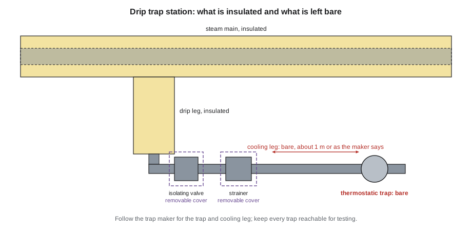
- Thermostatic traps, balanced pressure and bimetallic, open when the condensate around the element cools below steam temperature. They are normally left bare, and often need a length of bare pipe ahead of them, a cooling leg, so the condensate cools enough to open the trap. The maker gives the length; about 1 m (3 ft) or more is common.
- Thermodynamic, or disc, traps open and close as the steam above the disc cools and condenses. They are normally left bare. Many come with a cap over the disc chamber that steadies them against rain and wind; do not insulate over the cap or replace it with insulation unless the maker supplies an insulating cover for that trap.
In every case, the trap must stay accessible for testing and replacement. Traps are checked regularly with ultrasonic and temperature instruments, and a trap buried in insulation cannot be tested. The usual pattern on a trap station, the trap with its isolating valves, strainer and test or bypass valves, is to insulate the drip leg and the piping up to the station, insulate or cover the strainer and valves as the specification calls for, and leave the trap itself and any cooling leg bare.
Outdoors, where freezing is the concern, the answer can change: some specifications call for traps and their condensate lines to be insulated and heat traced to prevent freezing, using covers or trap insulation kits from the trap maker. That is a design decision; follow the drawings and the trap maker. Never stuff loose insulation around a trap on your own initiative because it looks bare.
Worked problem
A cooling leg
A balanced pressure thermostatic trap at the end of a Kellerton tracer line needs at least 1 m of bare pipe ahead of it, according to the maker. The trap is 300 mm after a tee from the insulated header drop. How much of the drop below the tee must be left bare?
Show solution
- Bare pipe needed ahead of the trap: 1 m = 1,000 mm.
- Already bare between the tee and the trap: 300 mm.
- Additional bare pipe needed above the tee: 1,000 − 300 = 700 mm.
Answer: The insulation on the drop must stop 700 mm above the tee, so that 1 m in total is bare ahead of the trap. Devon finishes the end of the insulation with a cap and writes the reason on his sketch, because the next person to see a bare length of steam pipe will want to insulate it.
Note: Bare cooling legs and traps are hot. Where they are within reach of people, the specification may call for a guard, a cage of expanded metal standing off the pipe, rather than insulation. A guard gives personnel protection without slowing the cooling.
Unions and threaded connections
A union is a threaded fitting that lets a section of small pipe be removed without turning the pipe. It is there to be opened. On hot service, insulate up to the union and leave the union nut accessible, or cover it with a short removable section. On cold service, a bare union sweats, so cover it with a removable, sealed section or a small preformed cover that can be cut free and replaced with tape. Threaded connections at equipment, such as a coil or a trap, are treated the same way.
Expansion joints and flexible connectors
Expansion joints absorb the thermal movement of long pipe runs, and flexible connectors absorb vibration and misalignment at pumps and equipment. Both must move freely. Insulation that binds them, or that is fixed to both sides of a moving joint, will be torn apart, and in the worst case it can stop the joint from doing its job and overload the pipe.
- Bellows expansion joints: insulate with a removable cover that is fixed to one side only and slides over the pipe insulation on the other, with enough length to allow the full movement shown on the drawings. Never fill the convolutions of a bellows with insulation unless the joint maker allows it.
- Slip-type expansion joints: keep the packing gland and any injection fittings clear, and allow for the full travel of the slip.
- Flexible connectors at pumps: use flexible insulation, such as elastomeric sheet on cold service or a removable blanket on hot, that can bend with the connector; on cold service, seal it to the pipe insulation on each side with a flexible joint.
- Pipe loops and offsets that take up expansion: insulate them as pipe, but check that the insulation at the elbows will not be crushed against nearby steel or walls when the pipe moves. INS-130 lesson 9 showed how to estimate the movement.
Gauges, thermometers and test ports
Instruments on piping must be read, and many must be removed for calibration. The general rule is to insulate up to the instrument and leave its face, its connection and its isolation valve accessible:
- Pressure gauges: insulate the pipe and the branch to the gauge valve; leave the gauge valve, the gauge and any siphon on steam lines clear. A steam gauge siphon must stay bare so it keeps a water seal that protects the gauge.
- Thermometers in wells: insulate around the well and leave the thermometer head clear. Where the insulation is thick, the thermometer needs a well with a long enough lagging extension to put the head outside the insulation; if it is too short, report it.
- Test ports, the small self-sealing plugs used for checking pressure and temperature on hydronic systems: leave the cap exposed, with the insulation finished neatly around it, so a probe can be pushed in without cutting anything.
- Flow meters, balancing valves and their measuring ports: insulate the body as a valve and leave the ports, the dial and the handle clear.
- Transmitters, switches and their tubing: do not insulate the electronics; insulate tubing only if the specification says so, usually with flexible insulation.
Vents, drains and sight glasses
- Automatic air vents release air through a small port at the top. They must breathe: never cover the vent cap or the vent outlet.
- Manual air vents and drain valves: insulate up to the valve and leave the valve, its cap and its outlet clear.
- Sight glasses and flow indicators: leave the glass visible. On cold service, the frame around the glass can be insulated and sealed, but the glass itself will fog or frost; that is expected.
- Relief valve discharges and drains, vacuum breakers and rupture discs: leave clear and unobstructed.
Nameplates, tags and markings
Valves, strainers, traps and instruments carry nameplates, tags and flow arrows that operators and inspectors must read. Pressure vessel and relief valve nameplates in particular must stay visible. If insulation covers a nameplate, cut a neat window in the insulation and finish its edges, or fix a copy of the information to the outside of the insulation where the specification allows it. Valve tags, the numbered brass or plastic discs hung on valve handwheels, must be left on the valve and visible; never cut them off to fit a cover. A removable cover should be tagged with the same number as the item under it.
| Specialty | Hot service | Cold service |
|---|---|---|
| Y-strainer | Body insulated; chamber cover removable; cap and blowdown clear | All insulated including cap; removable, resealed cover |
| Float and thermostatic trap | May be insulated per maker; keep accessible | Not usually on cold service |
| Thermostatic or disc trap | Left bare, with any cooling leg; guard if within reach | Not usually on cold service |
| Union | Up to the union, nut accessible or removable section | Removable sealed section |
| Expansion joint | Removable cover fixed one side only, allows travel | Flexible, sealed, allows travel |
| Gauge or thermometer | Up to the valve or well; face clear | Up to the valve or well; sealed around the stem |
| Automatic air vent | Vent cap and outlet clear | Vent cap and outlet clear |
| Nameplate or tag | Visible; window or copy on the outside | Visible; window sealed at its edges |
Common mistakes
MistakeInsulating a thermostatic or disc trap because it looks bare.
InsteadLeave it bare, with any cooling leg the maker requires, unless the drawings call for a trap cover.
MistakeCovering a strainer cap so the screen cannot come out.
InsteadStop the insulation at the cap or make the chamber cover removable, and keep the screen path clear.
MistakeFixing an expansion joint cover to both sides.
InsteadFix it to one side only and let it slide over the other.
MistakeCovering an automatic air vent cap.
InsteadLeave vent caps and outlets clear so they can breathe.
MistakeBurying a nameplate or cutting off a valve tag.
InsteadKeep nameplates visible and tags on the valve, and tag removable covers to match.
MistakeInsulating over a steam gauge siphon.
InsteadLeave the siphon bare so it keeps its water seal.
Summary and key terms
- Specialties need a decision: insulate, leave bare or insulate with a removable section.
- Strainers: insulate the body and chamber, make the chamber cover removable and keep the cap, blowdown and screen path clear.
- Float traps may be insulated; bucket traps lightly per the maker; thermostatic and disc traps are normally left bare, with any cooling leg.
- Unions, expansion joints and flexible connectors must stay accessible or free to move.
- Gauges, thermometers, test ports, meters, vents, drains and sight glasses must stay readable and usable.
- Nameplates and tags stay visible; removable covers are tagged to match the item under them.
- Y-strainer
- A strainer with a screen chamber set at an angle to the line, closed by a cap.
- Blowdown valve
- A small valve on a strainer cap used to flush the screen.
- Steam trap
- A device that lets condensate and air out of a steam system while holding steam in.
- Cooling leg
- A length of bare pipe ahead of a thermostatic trap that lets condensate cool before the trap.
- Drip leg
- A short vertical pipe below a steam main that collects condensate for a trap.
- Union
- A threaded fitting that lets small pipe be disconnected without turning it.
- Gauge siphon
- A looped tube under a steam pressure gauge that holds water to protect the gauge.
- Test port
- A small self-sealing plug for checking pressure or temperature with a probe.
Practice problems
Work each problem on paper first, then reveal the answer to check.
Name two parts of a Y-strainer that must be left accessible.
Show answer
The cap and the blowdown valve, and the path to pull the screen out.
Why are thermostatic traps usually left bare?
Show answer
They open when the condensate cools; insulation slows the cooling and delays opening.
A trap needs 1.2 m of bare pipe and is 400 mm below the tee. How far above the tee must the insulation stop?
Show answer
1,200 − 400 = 800 mm.
How should an expansion joint cover be fastened?
Show answer
To one side only, sliding over the pipe insulation on the other.
What must stay clear on an automatic air vent?
Show answer
The vent cap and its outlet.
Lesson quiz · 5 questions
Score 60% or more to complete this lesson.
Create a free account to save your progress, take quizzes and earn a certificate.