
INS-210 · Lesson 12 of 12 · 26 min
Case study: a valve station
▶ Video coming soon A video version of this lesson is on the way.
The week after the outage, Kellerton gave Coldstream its first job under the new rule. The pressure-reducing valve station that fed the plant's sanitation hot water heat exchanger had been rebuilt by the mechanical contractor during the shutdown: a new pressure-reducing valve, new isolation valves, a new strainer and a new bypass. All the old insulation had come off, and everything was bare. Lou Brisebois wanted it insulated that week, with removable covers on everything the plant's standard called for, and a list he could give his mechanics. Raj Sandhu priced it on the Friday. On Monday, November 9, 2026, Marcel and Devon were at the station with their measuring bag.
This lesson follows the job from start to finish: what the station is and what it does, the plant standard and the decisions it forced, the takeoff and the estimate, measuring for removable blankets, insulating the pipe and fittings, the details at the specialties, inspection and handover. It brings together every lesson in this course.
The station
A pressure-reducing valve station takes steam at the main header pressure and delivers it at a lower pressure to equipment that needs less. The Kellerton station reduced steam from the header, at 1,035 kPa (150 psig) and about 186 °C (366 °F), to about 103 kPa (15 psig) and about 121 °C (250 °F) for the heat exchanger. Following the steam through it:
- An NPS 3 high-pressure inlet from the header, with two long-radius elbows dropping to the station.
- A drip leg ahead of the station, with a thermodynamic trap to drain condensate.
- An NPS 3 flanged gate valve to isolate the station, then an NPS 3 flanged Y-strainer with a blowdown valve.
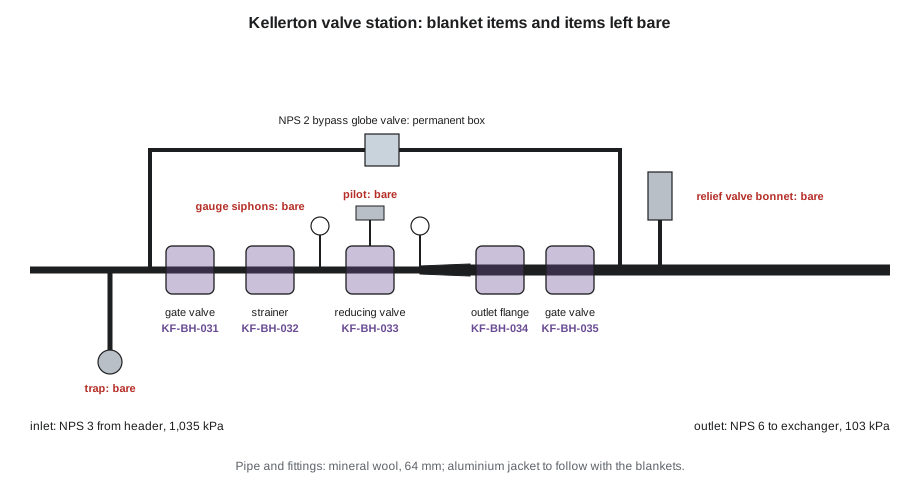
- The NPS 3 pilot-operated pressure-reducing valve, flanged, with its pilot, sensing line and diaphragm housing.
- A concentric expander from NPS 3 to NPS 6, because low-pressure steam takes up more space.
- An NPS 6 flanged gate valve on the outlet, a pressure gauge on each side of the reducing valve, each on a siphon, and a safety relief valve on the low-pressure side.
- An NPS 2 bypass around the station, through two reducing tees, two elbows and an NPS 2 globe valve, so the plant can run on the bypass while the reducing valve is serviced.
The plant standard and the decisions
Kellerton's insulation standard for steam, which Raj had in the bid documents, called for mineral wool pipe covering with an aluminium jacket, 64 mm (2 1/2 in) thick on NPS 2 to NPS 6 and 76 mm (3 in) on NPS 8 and up, and removable covers on all steam valves larger than NPS 2. Applying it to the station took some decisions, which Marcel and Devon worked through with Lou on Monday morning:
- Removable blankets, as the standard required, on the NPS 3 gate valve, the NPS 3 strainer, the reducing valve body and the NPS 6 gate valve. Lou added the flanged joint at the reducing valve outlet, which his mechanics open whenever the valve is serviced. Five blankets in all, tagged KF-BH-031 to 035.
- A permanent valve box on the NPS 2 bypass globe valve, since the standard asked for covers only above NPS 2.
- The reducing valve's pilot, sensing line and diaphragm housing left clear, as lesson 5 described for control valves; the blanket for the main valve body to stop below the diaphragm housing.
- The safety relief valve's bonnet, lever and discharge left clear; only the inlet nozzle insulated.
- The thermodynamic trap and the gauge siphons left bare, as lesson 7 explained. The drip leg to be insulated down to the trap's isolating valve.
- The aluminium jacket to go on later, with the blankets, so the jacket laps could be arranged around the blanket ends. Until then, the pipe insulation would be finished with its factory jacket and banded.
Lou asked one more question: could the station run while the insulators worked? It had to, because the heat exchanger served the sanitation system. So the pipe was live, at full temperature. Marcel's rules for the week were the same as for any hot work on live lines: gloves and long sleeves at all times, no leaning on or reaching across bare pipe, no tools set down on hot metal, work from a stable platform, one person never working alone at the station, and the cement used only within its surface temperature range.
The takeoff and the estimate
Raj's estimate, built from Devon's survey sheet and the plant drawings, listed each item with Coldstream's typical production rates for live steam in a congested station. These rates are company figures, not industry values:
Worked problem
The estimate
The pipe is 6.5 m of NPS 3 high-pressure, 3.2 m of NPS 2 bypass and 5.0 m of NPS 6 low-pressure, at 0.6 h per metre for NPS 2 and 3 and 0.8 h per metre for NPS 6. Fittings: two NPS 3 elbows at 1.0 h each, two NPS 6 elbows at 1.5 h, two NPS 2 elbows at 0.75 h, two reducing tees at 1.25 h, one expander at 1.5 h, one NPS 2 globe valve box at 2.5 h, the drip leg at 1.0 h and measuring five blankets at 0.75 h each. Add 4 h for set-up, hot-work precautions and clean-up. What is the estimate?
Show solution
- Pipe: (6.5 + 3.2) × 0.6 + 5.0 × 0.8 = 5.82 + 4.0 = 9.82 h.
- Elbows: 2 × 1.0 + 2 × 1.5 + 2 × 0.75 = 6.5 h.
- Tees, expander, valve box and drip leg: 2 × 1.25 + 1.5 + 2.5 + 1.0 = 7.5 h.
- Blanket measuring: 5 × 0.75 = 3.75 h.
- Subtotal: 9.82 + 6.5 + 7.5 + 3.75 ≈ 27.6 h; with 4 h added: about 31.6 h.
Answer: About 32 hours: two people for two full days and a morning. Raj scheduled Marcel and Devon from Monday to Thursday, with inspection on Friday.
Monday: measuring for blankets
Monday morning went to the walk with Lou and the decisions above. In the afternoon, Marcel and Devon measured the five blanket items, using the sketch sheets and the lettered dimensions from lesson 2. On the live station, they measured diameters by wrapping a tape around the flanges and bodies with gloved hands, keeping the tape moving, and took bonnet heights with a rule held off the metal. Each sketch recorded the valve type, size and class, stem direction, operator, the height to the packing gland or, on the reducing valve, to the bottom of the diaphragm housing, the adjoining insulation diameter of 216.9 mm (8 1/2 in) on the NPS 3 and 296.3 mm (11 5/8 in) on the NPS 6, and the clearances. A tag was wired to each item. Raj sent the sketches to the blanket fabricator on Tuesday morning; delivery was promised for Monday, November 30.
The strainer's blanket got a separate flap over the screen chamber, closing at the cap, so the mechanics could open the chamber cover alone to blow down or pull the screen. The reducing valve's blanket was made in two pieces, one for the body and one for the outlet flange, so either could come off without the other.
Tuesday and Wednesday: pipe, elbows and the expander
With the blankets ordered, the rest of the station was insulated permanently. Marcel and Devon worked from the header down: the NPS 3 inlet and its two elbows, the drip leg, the straight pipe between the blanket items, the expander, the NPS 6 outlet and its elbows, then the bypass. At every flanged joint that would get a blanket, Devon stopped the pipe insulation short by the cutback from lesson 6, measured from his sketch of the stud lengths, and capped the ends with metal end caps so the blankets would have a firm, clean end to overlap.
The elbows followed lessons 3 and INS-130: three-piece mitres on the NPS 2 and NPS 3 elbows, four pieces on the NPS 6, each worked out on Devon's pad before the first cut and checked dry before wiring.
Worked problem
The expander
The NPS 3 × 6 concentric expander is 140 mm long. Both sides have 64 mm covering. NPS 3 is 88.9 mm across and NPS 6 is 168.3 mm. Using the wedge method from lesson 4, cut from NPS 6 covering, what total width must be removed at the small end, and how wide is each of six wedges?
Show solution
- Outside diameters: 88.9 + 128 = 216.9 mm and 168.3 + 128 = 296.3 mm.
- Difference in circumference: π × (296.3 − 216.9) = π × 79.4 ≈ 249.4 mm.
- Six wedges: 249.4 ÷ 6 ≈ 41.6 mm each at the small end, tapering to zero over 140 mm.
Answer: Six wedges about 42 mm wide. The taper is steep for a short fitting, so Marcel had Devon cut the NPS 6 section into two halves and wedge each half separately, which let each half close cleanly without the seam fighting the wedges.
On Wednesday afternoon, Devon built the box on the bypass globe valve, following lesson 5, and found the job's first surprise: the globe valve had been installed with its stem pointing sideways, toward the wall, not up as on the drawing. The box he had cut on Tuesday evening, with its bonnet sleeve on top, was useless. He measured again, recut the sleeves with the bonnet opening on the side and stopped the bonnet insulation below the packing gland measured along the stem, with 25 mm (1 in) clear. The rebuild cost about two hours.
The specialties
The specialties took less time than anything else and more thought. On the drip leg, the insulation ran down to the trap's isolating valve and stopped, with an end cap. The thermodynamic trap and its cap stayed bare, as its maker requires, and so did the short nipple below the isolating valve. Devon's first attempt had carried the insulation over the isolating valve to the trap; Marcel had him cut it back so the valve handle could be turned and the trap tested and changed. The two gauge siphons stayed bare. The relief valve's inlet nozzle was insulated up to the base of the valve, with the body above it, the bonnet, the lever and the discharge left clear, and Devon checked that nothing he had installed touched the discharge pipe. Every item left bare on purpose went on Devon's list for Lou, with the reason.
Thursday: finishing and a meeting
Thursday morning was banding, end caps, a last check of every cutback against the sketches and cleaning up. In the afternoon, Devon went with Bernie to the meeting on the new kettle room steam line, the one described in INS-120, where he answered Bernie's question about why the header had 76 mm (3 in) of insulation. Marcel finished the station alone, which, with the plant's rule that nobody works alone at live steam, meant he did the paperwork in the control room and left the last two end caps for Friday morning.
Friday: inspection and handover
On Friday, November 13, Bernie and Lou walked the station with Devon's checklist from lesson 11. They found three items:
- Two cutbacks at the NPS 6 gate valve had end caps missing: the two Marcel had left for the morning. Devon fitted them before the walk was over.
- The wire tag on blanket item 033, the reducing valve body, had been knocked off when the mechanical contractor adjusted the pilot. Devon rewired it.
- The bypass box's bonnet sleeve stopped 25 mm (1 in) below the gland, as specified, but its edge was raw. Devon finished it with a bead of finishing cement.
The station's thermal check had to wait for the blankets, but the permanent insulation read as expected: Devon's infrared thermometer, set for the factory jacket, showed the pipe insulation surface within a few degrees of the room, and every bare item exactly where the list said it would be bare.
Worked problem
How did the estimate do?
The time sheets showed 36 hours on the station. The estimate was about 32 hours. What was the overrun, as hours and per 100 hours estimated, and what caused it?
Show solution
- Overrun: 36 − 32 = 4 hours.
- Per 100 estimated hours: 4 ÷ 32 × 100 = 12.5.
- Causes from the daily notes: about 2 hours rebuilding the globe valve box for the sideways stem, about 1 hour cutting back the drip leg insulation, the rest in end caps and finishing.
Answer: Four hours over, 12.5 per 100. Both main causes were avoidable: checking the stem direction against the drawing on Monday, and deciding what stays bare before starting. Raj added "confirm stem directions on site" to Coldstream's station estimating sheet.
Before leaving, Devon gave Lou the handover list: the five blanket tags with their locations and what each covers, a note that the blankets would arrive on November 30 and be fitted with the aluminium jacket that week, the items left bare on purpose and why, and the product data for the mineral wool, the end caps and the cement. Lou put the list in the boiler house binder and asked for the same thing for the rest of the survey items. Marcel looked at Devon and said, "That's the next quote, then."
What the job shows
The station was small, but it used every part of this course. The survey and the heat loss reasoning of lesson 1 started it. Measuring for blankets followed lesson 2, the elbows lessons 3 and INS-130, the expander lesson 4, the valve box lesson 5, the cutbacks lesson 6, the specialties lesson 7, the blankets lesson 8, the cement edge lesson 9 and the inspection lesson 11. The only lesson it did not use was lesson 10, because the station was hot; on a chilled water or refrigeration station, every joint would also have needed sealing and every fitting a vapour stop on each side. The lessons that cost time were the ones that are easiest to skip: checking the fitting against the drawing, and deciding what stays bare.
Common mistakes
MistakeAssuming the stem direction from the drawing.
InsteadConfirm the stem direction and operator of every valve on site before cutting.
MistakeInsulating over an isolating valve to reach a trap.
InsteadStop at the valve so it can be operated and the trap tested and changed.
MistakeLeaving the end caps for later at blanket cutbacks.
InsteadFinish every cutback end as you go, so blankets have a clean end to overlap.
MistakeWorking alone at a live steam station.
InsteadFollow the plant's rule: never work alone at live steam.
MistakeHanding over a station without a list of covers and bare items.
InsteadGive the owner the tagged blanket list, bare items with reasons and product data.
Summary and key terms
- A pressure-reducing valve station gathers valves, a strainer, a reducing valve, an expander, a bypass, a trap, gauges and a relief valve in a small space.
- The plant standard set thickness, finish and which valves got removable covers; applying it took decisions on each item.
- Blanket items were measured with lettered sketch sheets on Monday, tagged, and ordered for delivery three weeks later.
- Pipe, elbows, the expander and the bypass box were insulated permanently, with cutbacks capped at every blanket item.
- The trap, gauge siphons, reducing valve pilot and relief valve bonnet were left bare on purpose and listed.
- Inspection found three small items; the overrun came from a sideways stem and a cutback at the trap, both avoidable.
- Pressure-reducing valve station
- An assembly of valves and fittings that reduces steam or water to a lower pressure.
- Pilot-operated valve
- A valve whose main valve is opened and closed by a small pilot valve that senses pressure.
- Bypass
- A pipe and valve around a station that lets the system run while the station is serviced.
- Expander
- A reducer installed so the flow goes from the small end to the large end.
- Production rate
- The hours a crew typically takes per unit of work, such as per metre or per fitting.
- Overrun
- The amount by which actual hours exceed the estimate.
Practice problems
Work each problem on paper first, then reveal the answer to check.
Why was the reducing valve's pilot left clear?
Show answer
Like a control valve actuator, it must not be buried in insulation and must be reachable for adjustment.
Name three items at the station that were left bare on purpose.
Show answer
The thermodynamic trap, the gauge siphons, the reducing valve pilot and the relief valve bonnet, lever and discharge.
Six wedges remove 249.4 mm at the small end of the expander. How wide is each?
Show answer
249.4 ÷ 6 ≈ 41.6 mm.
What caused most of the overrun?
Show answer
Rebuilding the globe valve box for a sideways stem, and cutting back the drip leg insulation.
What went on the handover list?
Show answer
Blanket tags and locations, delivery date, bare items with reasons and product data.
Lesson quiz · 5 questions
Score 60% or more to complete this lesson.
Create a free account to save your progress, take quizzes and earn a certificate.