
HSE-224 · Lesson 10 of 12 · 31 min
Batteries, solar, capacitors and other special systems
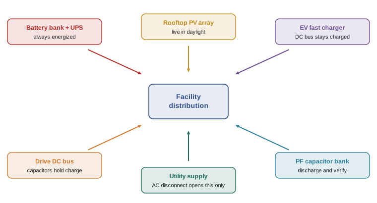
The approach boundaries, arc flash methods and electrically safe work condition described so far were developed mainly for AC distribution systems. Many workplaces now contain systems that behave differently: large battery banks, uninterruptible power supplies, solar photovoltaic arrays, electric vehicle chargers, variable frequency drives and capacitor banks, and data centres with very high fault currents. Each of these can store energy, generate it or back-feed it, which defeats the simple idea of opening a disconnect. This lesson highlights the special hazards and controls at an awareness level. Work on these systems requires specific qualification and the manufacturer's procedures.
Why special systems are different
Three features make these systems harder to make safe:
- They can be energized without a utility connection. A battery is always charged to some extent; a solar module produces voltage whenever light falls on it; a capacitor holds charge after the supply is removed.
- Many are DC. DC arcs have no current zero and can be harder to interrupt, DC protective devices may clear more slowly, and IEEE 1584 does not cover DC arc flash calculations.
- They often involve multiple sources and power electronics, so energy can flow in either direction and controls may re-energize circuits automatically.
Stationary batteries and UPS systems
Battery banks are found in substations, telecommunications facilities, data centres, hospitals and industrial control rooms, usually at 48 V, 125 V or 250 V DC for control and telecom systems and up to several hundred volts for UPS systems. They present shock, arc flash and chemical hazards. CSA Z462 includes requirements for safety-related maintenance of batteries and battery rooms, and the Canadian Electrical Code Section 26 covers battery installations. Lead-acid batteries release hydrogen when charging, which is flammable in air at concentrations of about 4 % and above, so battery rooms need ventilation and ignition control. Electrolyte is corrosive, so eyewash and face protection are needed. Lithium-ion batteries can enter thermal runaway, releasing toxic, flammable gases and burning in a way that is very hard to extinguish.
A battery cannot be fully de-energized. Opening the battery breaker removes the battery from the load, but the battery itself, and every intercell connector, remains energized. Work on batteries is therefore usually done with the battery partly sectionalized, using insulated tools, rubber insulating gloves rated for the DC voltage, and covers over terminals that are not being worked on.
Worked problem
Battery string voltage and fault current
A UPS battery string consists of 40 valve-regulated lead-acid blocks, each rated 12 V nominal, with an internal resistance of about 4 mΩ per block. Estimate the nominal string voltage and the maximum short-circuit current at the string terminals, ignoring cable resistance.
Show solution
- String voltage: \( 40 \times 12 = 480 \) V DC nominal.
- Total internal resistance: \( 40 \times 0.004 = 0.16 \) Ω.
- Short-circuit current: \( I = V/R = 480 / 0.16 = 3{,}000 \) A.
- With cables and connections, the actual value is lower, but a few thousand amperes is enough for a significant DC arc.
Answer: About 480 V DC and up to about 3 kA of short-circuit current. The string is in the 301 V to 1 kV DC shock row and needs DC arc flash assessment.
DC arc flash PPE categories
Because IEEE 1584 does not cover DC, the standards provide a separate PPE category table for DC equipment, along with informative methods for estimating DC incident energy. The DC table applies to storage batteries, DC switchboards and other DC supply sources. In the 2024 editions, the lower voltage limit of the table was changed so that it applies to systems above 150 V DC, reflecting test data showing that lower-voltage systems, such as 125 V station batteries, are much less likely to sustain an arc at moderate fault currents. The table assumes a maximum arc duration of 2 s and a working distance of 455 mm.
| Available DC fault current | PPE category | Arc flash boundary |
|---|---|---|
| Less than 1.5 kA | 2 | 0.9 m |
| 1.5 kA to less than 3 kA | 2 | 1.2 m |
| 3 kA to less than 7 kA | 3 | 1.8 m |
| 7 kA to less than 10 kA | 4 | 2.5 m |
Worked problem
Using the DC table
For the 480 V DC UPS battery in the previous example, with an available fault current of about 3 kA at the terminals and a battery breaker that would clear within 2 s, what PPE category and arc flash boundary does the DC table give?
Show solution
- 480 V DC is above 150 V and up to 600 V, so the table applies.
- 3 kA falls in the 3 kA to less than 7 kA row (the row starts at 3 kA inclusive).
- The table gives PPE category 3 and an arc flash boundary of 1.8 m.
- If the actual fault current were 2.9 kA, the row would be category 2 with a 1.2 m boundary. Values close to a row boundary should be checked carefully.
Answer: PPE category 3 (at least 25 cal/cm²) with a 1.8 m arc flash boundary.
Solar photovoltaic systems
A solar array generates DC voltage whenever light falls on it. Opening the inverter's AC disconnect stops power flowing into the building but leaves the array wiring energized at up to 600 V DC on many older systems and 1,000 V DC or 1,500 V DC on newer commercial and utility systems. Section 64 of the Canadian Electrical Code covers PV installations and requires rapid shutdown on buildings, which reduces the voltage in array conductors within the building envelope when activated, mainly for firefighter safety. Rapid shutdown reduces but does not remove the hazard inside the array itself. Workers on PV systems must treat modules and string wiring as energized during daylight, use DC-rated meters and tools, and follow the manufacturer's and designer's procedures for isolation, which may include covering modules or working at night.
Ground faults in PV arrays are a particular hazard. A fault can leave a normally grounded conductor carrying current, or make normally ungrounded parts energized with respect to ground, so a worker who opens a connection can be placed in the circuit. Connectors must not be disconnected under load, because the DC arc that forms can be sustained.
Worked problem
PV string voltage in cold weather
A string of 20 modules has an open-circuit voltage of 49.5 V per module at 25 °C, and a temperature coefficient of voltage of −0.28 % per °C. Estimate the string open-circuit voltage at 25 °C and on a cold morning at −30 °C.
Show solution
- At 25 °C: \( 20 \times 49.5 = 990 \) V DC.
- Temperature difference: \( 25 - (-30) = 55 \) °C.
- Voltage increase: \( 55 \times 0.28\% = 15.4\% \).
- At −30 °C: \( 990 \times 1.154 \approx 1{,}142 \) V DC.
Answer: About 990 V DC at 25 °C and about 1,140 V DC at −30 °C. Cold, bright mornings produce the highest voltage, which may exceed a 1,000 V rating on meters, gloves and tools.
Electric vehicle chargers
Level 2 chargers operate on 208 V or 240 V AC single-phase, while DC fast chargers convert three-phase AC (often 600 V in Canada) to DC outputs of 400 V to 1,000 V. Inside a fast charger, the DC bus capacitors can stay charged after the input is opened, and some chargers include battery storage. Section 86 of the Canadian Electrical Code covers EV charging systems. Work inside chargers requires manufacturer-specific training, verification of the DC bus voltage after the specified discharge time, and DC-rated test equipment. The vehicle side is a separate hazard: EV battery packs at 400 V to 800 V DC cannot be switched off and require specific training to service.
Capacitors and drives
Capacitors store energy in proportion to their capacitance and the square of their voltage: \( E = \tfrac{1}{2} C V^2 \). Power factor correction banks, surge capacitors, drive DC buses and UPS filters can all store enough energy to cause a lethal shock or a damaging arc. CSA Z462 includes requirements for work on capacitors, including discharge, grounding and verification. Capacitors should be discharged through rated resistive discharge tools rather than shorted directly, and then grounded and verified.
Worked problem
Energy stored in a drive capacitor bank
A variable frequency drive has a DC bus capacitor bank of 4,700 µF charged to 810 V DC. How much energy is stored?
Show solution
- Convert capacitance: \( 4{,}700 \) µF \( = 0.0047 \) F.
- Apply the formula: \( E = \tfrac{1}{2} \times 0.0047 \times 810^2 \).
- \( 810^2 = 656{,}100 \), so \( E = 0.5 \times 0.0047 \times 656{,}100 \approx 1{,}542 \) J.
Answer: About 1,500 J, far more than enough to be lethal. The drive must be discharged and verified before its cover is opened, regardless of the input disconnect position.
Data centres and high fault current systems
Data centres combine many of these features: large transformers close to the load, low-impedance busways, high available fault currents at low voltage, UPS systems with large battery banks or flywheels, multiple redundant feeds and automatic transfer equipment designed specifically to keep power on. The pressure to avoid outages is intense, and contracts may impose penalties for downtime. These are exactly the conditions under which energized work is most often requested and least often justified. Redundant designs (for example, A and B feeds to every rack) exist so that one path can be de-energized for maintenance, and using that redundancy is usually the right answer.
Utilities and overhead lines
CSA Z462 does not cover installations under the exclusive control of electric utilities for generation, transmission and distribution. Utility workers follow utility-specific rules, such as the IHSA Electrical Utility Safety Rules in Ontario and the utility provisions of provincial OHS regulations. When a contractor in an industrial plant works near a utility-owned transformer or overhead line, the overhead line limits of approach and the utility's own rules apply, and the utility must be contacted for any work that could encroach on its equipment.
Microgrids, energy storage and bidirectional flow
Battery energy storage systems, combined heat and power plants, microgrids and vehicle-to-grid chargers are increasingly common in commercial and industrial facilities. They allow energy to flow in both directions: from the utility to the load, from the storage to the load, and from the facility back to the utility. For electrical workers, the practical consequences are that a panel may be energized from below as well as from above, that an outage of the utility supply may not de-energize anything, and that control systems may start generation or discharge storage automatically. The single-line diagram and the lockout procedure must show every source, and the electrically safe work condition must account for all of them. Large energy storage systems are covered by CSA C22.1 Section 64 and by fire codes that require hazard mitigation analysis, emergency response plans and coordination with the fire service.
Equipment from different manufacturers often uses different terms and procedures for isolation. Some inverters have internal DC disconnects; some require an external disconnect to be opened first; some keep their DC capacitors charged for minutes after shutdown. Workers should be trained on the specific equipment, keep the manufacturer's isolation procedure with the lockout procedure, and verify absence of voltage on both the AC and DC sides before starting work.
Because these systems are changing quickly, a practical rule is that any electrical system with a battery, an inverter or a generator should be assumed to have a second source until the drawings, the equipment labels and a test at the point of work prove otherwise.
Common mistakes
MistakeAssuming opening the battery breaker makes the battery safe.
InsteadThe battery remains energized; use DC-rated gloves, insulated tools and terminal covers.
MistakeTreating a PV array as dead because the inverter is off.
InsteadModules produce voltage whenever light falls on them.
MistakeDisconnecting PV connectors under load.
InsteadInterrupt current with the rated disconnect first; DC arcs can be sustained.
MistakeShorting a capacitor with a screwdriver to discharge it.
InsteadUse a rated resistive discharge tool, then ground and verify.
MistakeUsing IEEE 1584 results for DC equipment.
InsteadUse the DC table or an appropriate DC incident energy method.
Summary and key terms
- Batteries, PV, capacitors and EV chargers store or generate energy that a disconnect cannot remove.
- Battery rooms add hydrogen, electrolyte and thermal runaway hazards.
- A separate DC PPE category table applies above 150 V DC in the 2024 editions.
- PV string voltage rises in cold weather and may exceed equipment ratings.
- Capacitor energy equals one-half C V squared; drives can hold lethal energy.
- Data centre redundancy should be used to de-energize rather than to justify live work.
- Utility installations follow separate utility rules.
- Thermal runaway
- A self-sustaining heating reaction in a battery cell.
- Rapid shutdown
- A PV function that reduces array conductor voltage when activated.
- Open-circuit voltage
- The voltage of a PV module or string with no load connected.
- Temperature coefficient
- The percentage change in module voltage per degree of temperature.
- DC bus
- The internal DC circuit of a drive, UPS or charger, usually with large capacitors.
- Valve-regulated lead-acid (VRLA)
- A sealed lead-acid battery that recombines most of its gases.
- Intercell connector
- A conductor joining adjacent battery cells or blocks.
- Discharge tool
- A rated device with a resistor used to discharge capacitors safely.
- Redundant feed
- A second supply path that allows one path to be de-energized.
Practice problems
Work each problem on paper first, then reveal the answer to check.
What is the nominal voltage of 60 cells of 2 V each?
Show answer
120 V DC.
At what concentration does hydrogen become flammable in air?
Show answer
About 4 %.
What is the lower voltage limit of the 2024 DC PPE category table?
Show answer
Above 150 V DC.
What PPE category does the DC table give at 5 kA?
Show answer
Category 3.
Why does PV voltage rise on cold mornings?
Show answer
Module voltage has a negative temperature coefficient.
What energy is stored in 1,000 µF at 600 V?
Show answer
180 J, from 0.5 × 0.001 × 600².
What does rapid shutdown do?
Show answer
Reduces voltage in array conductors when activated, mainly for firefighter safety.
Name two hazards of lithium-ion batteries besides shock.
Show answer
Thermal runaway, toxic gas release and difficult fires.
Why should PV connectors not be separated under load?
Show answer
A sustained DC arc can form.
What is the best way to maintain one feed in a data centre with A and B feeds?
Show answer
De-energize one feed while the other carries the load.
Lesson quiz · 5 questions
Score 60% or more to complete this lesson.
Create a free account to save your progress, take quizzes and earn a certificate.