
FAT-110 · Lesson 9 of 12 · 22 min
Fire alarms and other building systems
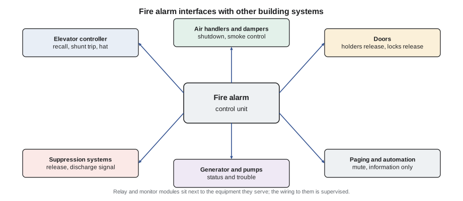
When the alarm sounds at Eastview General Hospital, a great deal happens that nobody hears. Fire doors swing shut along the corridor of the affected ward. Elevators that were carrying visitors stop at the nearest floor in their direction of travel, then return to the lobby and open their doors. Air handlers serving the ward shut down and their smoke dampers close, while stair pressurization fans start. Electrically locked doors on the exit route release. Overhead paging music stops so the emergency message can be heard. The security office's screen shows a floor plan with the alarm marked. All of it is triggered by the fire alarm system, but almost none of it is fire alarm equipment. This lesson introduces those connections, called emergency control functions or interfaces: what each one does, why it is there, who is responsible for each side, and how they are tested together. FAT-320 covers them in depth.
The interface idea
An interface is the point where the fire alarm system tells another system to do something, or where another system tells the fire alarm system something has happened. On the fire alarm side, it is usually a relay contact or a control module output that changes state on alarm; on the other side, it is an input on the elevator controller, the fan starter, the door hardware power supply or the smoke control panel. The fire alarm system is responsible for sending the right signal at the right time to the right place; the other system is responsible for doing the right thing when it gets the signal. Both sides have to be designed, installed and tested, and the drawing that shows the boundary between them is one of the most important documents in a building.
Standards require interface devices to be close to the equipment they control, so a long wire that could be damaged isn't the only thing connecting them, and require the wiring between the fire alarm control unit and the interface device to be supervised. If a cable to a control module is cut, the panel reports a trouble. The wire from the module's contact to the fan starter, a short run in the same room, is the other trade's responsibility.
Elevators
Elevators and fire don't mix. An elevator car can stop at a fire floor and open its doors into smoke, its shaft can carry smoke between floors, and water from sprinklers can make its brakes and controls unsafe. Elevator codes, CSA B44 in Canada, require elevators to be recalled when fire is detected, and the fire alarm system sends the signal. Smoke detectors in each elevator lobby, in the elevator machine room and, in some cases, in the hoistway are the inputs. When any of them operates, the system sends the cars to the designated level, usually the main entrance floor, where firefighters will arrive. If the detector that operated is on the designated level itself, the cars go instead to an alternate level. Once there, the cars park with doors open and can be operated only by firefighters with a special key.
Detectors in the machine room or the hoistway also tell the elevator controller to flash a firefighters' hat symbol in the car, warning firefighters that the elevator's own equipment may be affected by fire. Where sprinklers protect the machine room or hoistway, a heat detector placed close to each sprinkler is arranged to cut power to the elevator, through a device called a shunt trip, before water reaches it, so the car doesn't move with wet brakes. The heat detector is rated lower and responds faster than the sprinkler next to it, so the power goes off first. Riverlight Tower's elevator machine room has exactly this arrangement, and Gerry tests it each year with the elevator mechanic present.
| Input | Output to the elevator controller | Why |
|---|---|---|
| Elevator lobby detector, any floor but the designated level | Recall to the designated level | Keep cars away from the fire floor; deliver them to firefighters |
| Elevator lobby detector on the designated level | Recall to the alternate level | The designated level is where the fire is |
| Machine room or hoistway detector | Recall, and flash the firefighters' hat in the car | Warn that elevator equipment may be affected |
| Heat detector next to a machine room or hoistway sprinkler | Shunt trip: cut elevator power | Stop the car before water reaches its brakes and controls |
Air handling and smoke control
A large air handler moves thousands of litres of air a second around a building. If a fire starts in an area it serves, it can pick up smoke and spread it to every floor, so the fire alarm system shuts it down. Duct smoke detectors, mounted in the supply or return ducts of larger units, catch smoke inside the duct even if the room detectors haven't seen it yet. Shutdown is usually done by a relay that opens the fan's control circuit, and the fan's dampers close when it stops. In many buildings, any alarm shuts down the air handlers serving the fire area; in others, the sequence is more detailed.
Fire dampers and smoke dampers are different devices. Fire dampers, in ducts where they pass through fire-rated walls and floors, close by themselves when a fusible link melts, without any signal from the alarm system. Smoke dampers close to stop smoke moving through the ductwork and are controlled electrically, often by the fire alarm system, with switches that report whether each damper is open or closed. Combination fire and smoke dampers do both jobs. Their correct operation is checked by the HVAC contractor and, for the electrically controlled ones, in the integrated test.
Smoke control systems go further. Instead of just stopping fans, they run fans on purpose to manage smoke: pressurizing stairs so smoke can't enter them, exhausting smoke from the fire floor or an atrium, and supplying air to floors next to the fire to keep smoke out. Riverlight Tower and Eastview General Hospital have stair pressurization fans that start on alarm. Smoke control is designed by mechanical engineers and controlled through the fire alarm system or a dedicated smoke control panel, with a firefighters' control panel at the entrance that lets firefighters see and override every fan and damper. Testing it is a team effort involving the fire alarm technician, the HVAC contractor, the controls contractor and often the fire department.
Doors
Fire doors in corridors and stairs must be closed in a fire to keep smoke and flames out of exits, but in daily use, propped-open doors are convenient, and people wedge them open. Electromagnetic door holders solve this: a magnet on the wall holds the door open, and the fire alarm system cuts the magnet's power on alarm so the door's closer pulls it shut. The holder's power supply is controlled through a relay or a module, and on loss of power the doors close too, which is the safe way for them to fail.
Locked doors raise the opposite concern. Many buildings lock doors for security, with electric locks controlled by an access control system, but codes require that doors on exit routes let people out in an emergency. On alarm, the fire alarm system signals the access control system or directly cuts power to magnetic locks so that they release, and delayed-egress locks, which hold a door for a short time to alert staff, release fully. The rules for which doors may be locked and how they must release are set by the building code; the fire alarm technician's job is to make sure the release signal reaches every door that relies on it, and to test it. Willowbank School's front doors and Eastview's ward exits are both on that list.
Suppression, fuel and power
Lesson 8 described releasing panels for suppression systems and the signal from kitchen hood systems. The fire alarm system may also shut off fuel: gas valves to cooking equipment when the hood system discharges, fuel to boilers in some designs. It monitors the emergency generator, which supplies power to life safety systems when the utility fails, and the transfer switch that connects it, so that their status shows at the panel and the monitoring station. And in buildings with a fire pump, as Lesson 8 explained, the pump controller's signals come into the fire alarm panel.
Paging, mass notification and building automation
Background music and general paging systems must not compete with emergency messages. The fire alarm system sends a signal to mute the building's audio system when an alarm is active, so that horns or voice messages can be heard clearly. In buildings with mass notification systems, which can deliver messages about weather, security threats and other emergencies, the codes set priorities between fire alarm messages and mass notification messages, and the two systems are linked so that the higher priority message is heard. FAT-310 covers those rules.
Building automation systems, which run heating, cooling and lighting, often receive information from the fire alarm system, such as which zone is in alarm, so they can display it or adjust equipment. But the fire alarm system must not depend on the building automation system to perform its life safety functions, unless that equipment is listed and installed for the purpose. Fan shutdown for smoke, for example, is done through a hard-wired relay from the fire alarm, not by a message the automation system may or may not act on. When Sasha sees an interface marked 'BAS monitor only', it means the automation system is watching, not controlling.
Testing interfaces together
Each system can pass its own tests and the building can still fail. The fire alarm relay can operate correctly and the fan can still keep running, because a wire at the starter is on the wrong terminal or the starter has been switched to hand mode. That is why codes and standards now call for integrated testing, in which the whole chain from initiating device to final action is tested with every trade present. In Canada, CAN/ULC-S1001, the Standard for Integrated Systems Testing of Fire Protection and Life Safety Systems, sets out how such tests are planned, carried out and documented, and the building code requires it for new buildings with interconnected life safety systems.
The test plan follows the sequence of operation. For each input, the team operates the device and every trade watches its own equipment: the fire alarm technician confirms the panel and outputs; the elevator mechanic watches the cars recall; the HVAC technician confirms the fan stops and dampers close; the door hardware installer checks that every locked door releases. Each result is recorded with the time it took. Any failure is corrected and that part of the test repeated. The script below checks a log from Tamarind House's integrated test against the times the specification allows for each output.
# Integrated test log: did each output respond, and within the time the specification allows?
spec = {"door holders": 10, "elevator recall start": 10, "AHU-2 shutdown": 15, "stair fan start": 30, "maglock release": 5}   # seconds
log = [  # input operated, output, observed seconds (None = no response)
    ("3rd floor smoke detector", "door holders", 2),
    ("3rd floor smoke detector", "elevator recall start", 4),
    ("3rd floor smoke detector", "AHU-2 shutdown", 9),
    ("3rd floor smoke detector", "stair fan start", 41),
    ("3rd floor smoke detector", "maglock release", None),
]
for inp, out, t in log:
    limit = spec[out]
    if t is None:
        res = "NO RESPONSE - trace the interface"
    elif t <= limit:
        res = f"pass ({t} s, limit {limit} s)"
    else:
        res = f"SLOW ({t} s, limit {limit} s)"
    print(f"{inp} -> {out:22s} {res}")
fails = [o for i, o, t in log if t is None or t > spec[o]]
print("Retest after correction:", ", ".join(fails))3rd floor smoke detector -> door holders pass (2 s, limit 10 s) 3rd floor smoke detector -> elevator recall start pass (4 s, limit 10 s) 3rd floor smoke detector -> AHU-2 shutdown pass (9 s, limit 15 s) 3rd floor smoke detector -> stair fan start SLOW (41 s, limit 30 s) 3rd floor smoke detector -> maglock release NO RESPONSE - trace the interface Retest after correction: stair fan start, maglock release
Two items fail. The stair fan starts late because its variable speed drive is set to ramp up slowly, a setting the mechanical contractor changes. The magnetic locks on the ground floor didn't release at all; the cause turns out to be a module wired to the wrong input on the access control panel. Both are corrected and retested the same afternoon, and the corrected results go into the integrated test report.
Who is responsible for what
Clear responsibility prevents the most common interface failure, which is everyone assuming someone else checked it. The fire alarm contractor is responsible for the fire alarm side: the devices, the program, the outputs and the supervised wiring to the interface device. Each other trade is responsible for its own equipment and its response. The designer is responsible for the sequence of operation that ties them together, and the owner, or the owner's commissioning agent, for making sure everyone tests together. Sasha's practical rule, which Gerry taught her on the first integrated test she attended, is never to sign off an interface she has only half seen: if she operated the relay but nobody watched the fan, the test isn't finished.
Worked problem
The fan that wouldn't stop
During Tamarind House's annual test, Sasha operates the 5th floor duct detector for AHU-3. The panel shows the alarm and the AHU-3 shutdown relay changes state, but the building manager says the fan is still running. What should she check, in order?
Show solution
- Confirm at the panel that the correct output point operated and that the module reports its relay as active.
- At the fan, check whether the starter is in automatic mode; a starter switched to hand mode ignores the control circuit.
- Check the control wiring from the module's contact to the starter terminals against the drawings; a contact on the wrong terminal or a jumper added during service would bypass it.
- With the HVAC technician, correct the fault on their side and repeat the test until the fan stops and its dampers close.
Answer: In this case the starter had been left in hand mode after a filter change. The HVAC technician returns it to automatic, the retest passes, and the report records both the fault and the fix.
Common mistakes
MistakeAssuming the fan stopped because the relay operated.
InsteadWatch the controlled equipment itself; an interface test isn't complete until the final action is seen.
MistakeUsing the building automation system for life safety control.
InsteadUse listed, hard-wired fire alarm outputs for life safety functions.
MistakeTesting elevator recall without the elevator mechanic.
InsteadCoordinate with the elevator contractor, who is responsible for the car's response.
MistakeForgetting to release locked exit doors.
InsteadEvery door that relies on fire alarm release is part of the test.
MistakeConfusing fire dampers and smoke dampers.
InsteadFire dampers close on a fusible link; smoke dampers are controlled and monitored electrically.
Summary and key terms
- Interfaces are where the fire alarm system tells other systems what to do, or receives their status.
- Elevator lobby, machine room and hoistway detectors recall elevators; heat detectors near sprinklers trigger shunt trip.
- The fire alarm shuts down air handlers, controls smoke dampers and starts smoke control fans.
- Door holders release to close fire doors; locked exit doors release on alarm.
- The fire alarm monitors generators and pumps, and may shut off fuel and mute paging.
- Building automation may watch but must not be relied on for life safety control unless listed for it.
- CAN/ULC-S1001 sets out integrated testing of all interconnected life safety systems.
- Each trade is responsible for its own side of an interface; testing is done together.
- Interface
- The connection point where the fire alarm system controls or monitors another system.
- Designated level
- The floor to which elevators are recalled, usually the main entrance level.
- Alternate level
- The floor used for recall when the fire is on the designated level.
- Shunt trip
- A device that cuts power to an elevator before sprinkler water reaches its equipment.
- Smoke damper
- An electrically controlled damper that stops smoke moving through ducts.
- Smoke control
- Fans and dampers run deliberately to manage smoke, such as stair pressurization.
- Integrated testing
- Testing interconnected life safety systems together, from input to final action.
Practice problems
Work each problem on paper first, then reveal the answer to check.
The elevator lobby detector on the designated level operates. Where do the cars go?
Show answer
To the alternate level.
Why must the shunt trip heat detector respond before the sprinkler next to it?
Show answer
So elevator power is cut before water reaches the brakes and controls.
What happens to doors held by electromagnetic holders if power fails?
Show answer
They close, which is the safe way to fail.
Who confirms the fan has stopped during an interface test?
Show answer
The HVAC technician watching the fan, with the fire alarm technician confirming the output.
Lesson quiz · 5 questions
Score 60% or more to complete this lesson.
Create a free account to save your progress, take quizzes and earn a certificate.