
ELEC-210 · Lesson 8 of 12 · 43 min
Transformers
The transformer is the reason AC power systems exist. It changes voltage up or down with efficiencies above 98%, has no moving parts, and can run for forty years. Electricians install and connect transformers constantly: pad-mounted utility units, dry-type transformers that step a building's distribution voltage down to 120/208 V for receptacles, control transformers in motor starters, buck-boost transformers that correct a supply voltage, and current transformers that feed meters and relays. This lesson explains how transformers work, the ideal transformer relationships, ratings, losses and efficiency, percent impedance and fault current, taps and polarity, single-phase and three-phase connections, autotransformers and buck-boost transformers, instrument transformers, and the rules for protecting and installing them safely.
How a transformer works
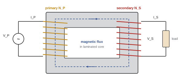
A transformer consists of two or more coils wound on a common iron core. An alternating voltage applied to the primary winding drives a small magnetizing current that produces an alternating magnetic flux in the core. The core guides almost all of that flux through the secondary winding, where the changing flux induces a voltage (mutual induction). Because the same flux links both windings, the voltage per turn is the same in each, so the voltages are in the ratio of the turns. A transformer works only with changing flux, so it does not transfer DC; a DC voltage applied to a primary would drive a large current limited only by the winding resistance and burn the winding out.
Cores are made of thin laminations of silicon steel, insulated from each other, to limit eddy currents induced in the core itself. Windings are copper or aluminium, insulated with enamel, paper or resin. Small and medium transformers in buildings are usually dry-type, cooled by air; large ones are immersed in mineral oil or less-flammable fluids for insulation and cooling.
The ideal transformer
Neglecting losses and leakage, the relationships are:
where \(a\) is the turns ratio. A step-down transformer (\(a > 1\)) lowers voltage and raises current; a step-up transformer does the opposite. Power in equals power out: the transformer trades voltage for current. The load current determines the primary current; with no load on the secondary, the primary draws only a small magnetizing current, typically 1 to 5% of rated current.
Worked problem
Step-down transformer
A single-phase transformer steps 600 V down to 120 V. The secondary supplies a 2.4 kW resistive load. Find the turns ratio, secondary current and primary current.
Show solution
- Turns ratio: \(a = 600/120 = 5\).
- Secondary current: \(2400/120 = 20\) A.
- Primary current: \(20/5 = 4\) A (check: \(600 \times 4 = 2400\) VA).
Answer: a = 5, 20 A on the secondary and 4 A on the primary.
Reflected impedance
An impedance \(Z_S\) connected to the secondary appears from the primary side as \(Z_P = a^2Z_S\). A 6 Ω load on the secondary of a 5:1 transformer looks like 150 Ω from the primary. This impedance transformation is used for matching in electronics and explains why impedances on the two sides of a transformer must be referred to a common side (or put in per unit, as in ELE-380) when calculating fault currents.
Ratings
Transformers are rated in volt-amperes (VA or kVA), not watts, because their heating depends on current, regardless of the load's power factor. The nameplate also gives the primary and secondary voltages, frequency, phases, percent impedance, insulation class and temperature rise, connection diagram, taps and, for three-phase units, the vector group or phase displacement. Rated currents follow from the kVA:
Worked problem
Rated currents of a dry-type transformer
A 75 kVA, three-phase, 600 V delta to 120/208 V wye transformer feeds a receptacle panel. Find the rated primary and secondary currents.
Show solution
- Primary: \(75{,}000/(\sqrt3 \times 600) = 72.2\) A.
- Secondary: \(75{,}000/(\sqrt3 \times 208) = 208\) A.
Answer: 72 A primary and 208 A secondary. This is one of the most common transformers in commercial buildings.
Losses, efficiency and heating
Real transformers have two kinds of losses:
- Core (no-load or iron) losses, from hysteresis (energy to reverse the magnetization of the steel each half cycle) and eddy currents in the laminations. They are present whenever the transformer is energized, regardless of load, and are nearly constant.
- Copper (load) losses, \(I^2R\) in the windings, which grow with the square of the load current. Harmonic currents add extra losses through eddy currents in the windings, which is why transformers serving nonlinear loads are derated or K-factor rated.
Efficiency is output power divided by input power. Because core losses are constant and copper losses rise with the square of load, efficiency peaks where the two are equal, typically at 35 to 50% of rated load for distribution transformers. Energy efficiency regulations in both Canada and the US set minimum efficiencies for distribution transformers at a specified load.
Worked problem
Transformer efficiency
A 75 kVA transformer has core losses of 250 W and full-load copper losses of 1200 W. Find its efficiency at full load and at 40% load, both at unity power factor.
Show solution
- Full load: output 75 kW; losses \(250 + 1200 = 1450\) W; \(\eta = 75{,}000/76{,}450 = 98.1\%\).
- 40% load: output 30 kW; copper losses \(1200 \times 0.4^2 = 192\) W; total losses 442 W; \(\eta = 30{,}000/30{,}442 = 98.5\%\).
Answer: 98.1% at full load and 98.5% at 40% load. The losses still become heat, about 1.45 kW at full load, which must be removed by ventilation of the room or enclosure; transformer rooms and electrical closets often need dedicated exhaust or cooling.
Insulation class and temperature rise limit loading. A dry-type transformer with 220 °C insulation might be rated for a 150 °C average winding rise over a 40 °C ambient; lower-rise designs (115 °C or 80 °C) run cooler, last longer and tolerate overloads better. Overloading or blocking ventilation shortens insulation life rapidly.
Percent impedance, regulation and fault current
A real transformer's windings have resistance and leakage reactance, together called its impedance, stated on the nameplate as a percentage. The percent impedance is the percentage of rated primary voltage that would drive rated current through a short-circuited secondary. It determines two important things:
- Voltage regulation: the drop in secondary voltage from no load to full load, roughly proportional to the impedance and to the load's power factor. Lower impedance gives better regulation.
- Fault current: with an infinite (stiff) source, the maximum fault current at the secondary is rated current divided by the per-unit impedance, \(I_{sc} = I_{rated}/Z_{pu}\). Lower impedance gives higher fault current, which equipment downstream must be rated to withstand and interrupt.
Worked problem
Available fault current
The 75 kVA transformer above (secondary 208 A) has an impedance of 4.5%. What is the maximum available fault current at its secondary terminals, assuming an infinite source?
Show solution
- \(I_{sc} = 208/0.045 = 4622\) A.
Answer: About 4.6 kA. Panelboards and breakers on this secondary must have short-circuit ratings at least this high; the actual value is a little lower because of the source impedance and the feeder, as ELE-380 explains, and fault current studies are required for larger services.
Taps
Most distribution transformers have taps on the primary winding to adjust the turns ratio when the supply voltage is consistently high or low. A typical arrangement provides two taps of 2.5% above nominal and four below (written 2 × 2.5% FCAN and 4 × 2.5% FCBN, "full capacity above/below nominal"). If the supply is consistently 3% low, connecting to the −2.5% tap uses fewer primary turns, raising the secondary voltage. Taps are changed only with the transformer de-energized; large utility transformers have on-load tap changers that adjust automatically.
Worked problem
Choosing a tap
A 600 V to 120/208 V transformer is supplied at 576 V, and the secondary measures 200 V at light load. Which tap brings the secondary close to 208 V?
Show solution
- Supply is \(576/600 = 0.96\), 4% low.
- The −5% tap (two steps below nominal) uses 5% fewer primary turns, raising the secondary by a factor of \(1/0.95 = 1.053\): \(200 \times 1.053 = 211\) V.
- The −2.5% tap gives \(200/0.975 = 205\) V.
Answer: Either −2.5% (about 205 V) or −5% (about 211 V) would work; the choice depends on the voltage drop expected at full load. With 3 to 4% drop under load, the −5% tap keeps the full-load voltage nearer 208 V.
Polarity
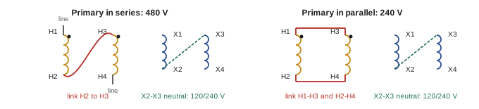
The relative direction of the windings determines whether the secondary voltage is in phase with the primary at given terminals. Transformer terminals are marked H1, H2 (high-voltage side) and X1, X2 (low-voltage side), so that at any instant H1 and X1 have the same polarity. In schematics this is shown with dots. Polarity matters when paralleling transformers, connecting single-phase units into three-phase banks, and connecting dual windings in series or parallel. Connecting windings with the wrong polarity can short-circuit a winding or produce voltages that cancel instead of adding.
Dual-voltage windings are common: a primary rated 240 × 480 V has two 240 V coils connected in parallel for 240 V or in series for 480 V, and a secondary rated 120/240 V has two 120 V coils in series with the centre tap as neutral. The nameplate diagram shows which terminals to link.
Three-phase transformers
Three-phase transformation uses either three single-phase transformers or one three-phase unit with three windings on a common core. The windings on each side can be connected in delta or wye:
| Connection (primary-secondary) | Typical use | Notes |
|---|---|---|
| Delta-wye | Most common building step-down: 600 V delta to 120/208 V wye | Provides a neutral; 30° phase shift; blocks triplen harmonics from the primary |
| Wye-delta | Utility step-up at generating stations; some industrial supplies | 30° phase shift; no secondary neutral |
| Delta-delta | Industrial three-wire systems | Can operate as open delta if one unit fails |
| Wye-wye | Utility distribution with grounded neutrals | Needs grounded neutrals or a tertiary winding to handle triplen harmonics |
The secondary of a delta-wye transformer is a separately derived system: its neutral must be grounded and bonded at the transformer or the first disconnect, as covered in ELEC-120.
Open delta
Two single-phase transformers connected in an open delta (V-V) can supply three-phase power, either as a planned economy or when one unit of a delta-delta bank fails. An open delta can carry only 57.7% (\(1/\sqrt3\)) of the capacity of the full three-transformer bank, or 86.6% of the combined rating of the two transformers used.
Worked problem
Open-delta capacity
A delta-delta bank of three 50 kVA transformers supplies 130 kVA of three-phase load. One transformer fails. Can the remaining two carry the load as an open delta?
Show solution
- Full bank: 150 kVA. Open delta: \(150 \times 0.577 = 86.6\) kVA (or \(2 \times 50 \times 0.866\)).
Answer: No: the open delta can carry about 87 kVA, so load must be reduced to that level until the failed unit is replaced, or the remaining transformers will overheat.
Autotransformers and buck-boost transformers
An autotransformer has a single winding with a tap, so part of the winding is common to primary and secondary. It is smaller and cheaper than a two-winding transformer for small voltage changes, but it provides no isolation between input and output. Variable autotransformers are used in test benches; reduced-voltage autotransformer starters reduce motor starting current (ELEC-310).
Buck-boost transformers are small two-winding transformers with low-voltage secondaries (typically 12, 16, 24 or 32 V) that are connected as autotransformers to raise (boost) or lower (buck) a supply by a few percent, for example to run 230 V equipment from a 208 V supply. Because the transformer carries only the boost voltage, a small unit handles a large load: the kVA required is the load current times the secondary (buck or boost) voltage.
Worked problem
Sizing a buck-boost transformer
A single-phase, 230 V, 40 A air conditioning unit must be supplied from a 208 V circuit. A buck-boost transformer with a 24 V secondary is connected to boost. What output voltage results, and what kVA rating is needed?
Show solution
- Output: \(208 + 24 \times (208/240) = 208 + 20.8 = 228.8\) V (the 24 V rating is at a 240 V primary, so at 208 V the secondary gives 20.8 V).
- Required rating: load current times boost voltage: \(40 \times 20.8 = 832\) VA; choose a 1 kVA unit.
Answer: About 229 V, adequate for 230 V equipment, using a transformer rated only about 1 kVA for a 9 kVA load. The unit must still be protected and installed as a transformer, and codes apply autotransformer rules to it.
Instrument transformers
Current transformers (CTs) and potential (voltage) transformers (PTs or VTs) reduce high currents and voltages to standard levels, typically 5 A or 1 A and 120 V, for meters, relays and controllers. A CT's primary is the power conductor passing through its window, and its secondary current is the primary current divided by its ratio: a 400:5 CT produces 5 A when 400 A flows.
A CT secondary must never be open-circuited while primary current flows. The CT is designed to drive current into a low-impedance burden; with the secondary open, the primary current becomes all magnetizing current, saturating the core and inducing a dangerously high voltage, possibly thousands of volts, across the open terminals, which can injure workers and destroy the CT. CT circuits are therefore fitted with shorting terminal blocks that short the secondary before a meter or relay is removed.
Installation and protection
The Canadian Electrical Code (Section 26) sets requirements for transformers, including maximum overcurrent protection on the primary, and on the secondary where required, as percentages of the transformer's rated currents; working space and ventilation; separation from combustible materials; vault requirements for large oil-filled units indoors; and grounding of the secondary system. Secondary conductors between the transformer and their overcurrent device must be protected and kept short.
Energizing a transformer draws a magnetizing inrush current of 8 to 12 times rated current (sometimes more for small units) for a few cycles, as the core is driven into saturation depending on the point on the voltage wave at switching. Primary breakers and fuses must ride through inrush without tripping, which is why their instantaneous settings and time-current characteristics are chosen with inrush in mind.
Worked problem
Primary protection
For the 75 kVA, 600 V primary transformer (72.2 A primary), the code generally permits primary-only protection at not more than 125% of rated primary current, with allowance for the next standard size. What breaker rating is permitted?
Show solution
- \(1.25 \times 72.2 = 90.3\) A; the next standard size is 100 A.
Answer: A 100 A breaker, subject to the conductor sizing and inrush ride-through, with the secondary conductors protected as the code requires.
Lesson 9 continues with three-phase connections, banks, paralleling and testing, and Lesson 11 extends the fault current calculation from the transformer terminals to the rest of the system.
Common mistakes
MistakeRating transformers in kW.
InsteadTransformers are rated in kVA because heating depends on current regardless of power factor.
MistakeOpen-circuiting a CT secondary under load.
InsteadShort the secondary first with the shorting block; an open CT develops lethal voltage.
MistakeConnecting dual windings without checking polarity.
InsteadFollow H1/X1 markings and the nameplate diagram; wrong polarity cancels voltage or shorts a winding.
MistakeExpecting an open delta to carry two-thirds of the bank rating.
InsteadIt carries only 57.7% of the full bank rating.
MistakeForgetting to ground the neutral of a delta-wye secondary.
InsteadIt is a separately derived system; ground and bond the neutral as the code requires.
Summary and key terms
- Transformers transfer power by mutual induction through a laminated iron core; they do not pass DC.
- Ideal relationships: V_P/V_S = N_P/N_S = a, I_P/I_S = 1/a, VA in = VA out; reflected impedance a²Z.
- Ratings are in kVA; I = VA/V (single-phase) or VA/(√3 V_L) (three-phase).
- Core losses are constant; copper losses vary with load squared; efficiency peaks where they are equal.
- Percent impedance sets voltage regulation and fault current: I_sc = I_rated/Z_pu.
- Taps adjust the turns ratio, typically in 2.5% steps above and below nominal.
- Polarity markings (H1, X1, dots) govern series, parallel and bank connections.
- Delta-wye is the common building step-down; open delta carries 57.7% of full-bank capacity.
- Buck-boost transformers correct voltage by a few percent with small kVA ratings.
- Never open-circuit a CT secondary; protect transformers per code and allow for inrush.
- Transformer
- A device that transfers AC power between windings by mutual induction.
- Mutual induction
- Voltage induced in one coil by changing current in another.
- Turns ratio
- The ratio of primary turns to secondary turns.
- Laminations
- Thin insulated steel sheets forming the core to limit eddy currents.
- Core losses
- Hysteresis and eddy current losses present whenever the transformer is energized.
- Copper losses
- I²R losses in the windings, varying with load.
- Percent impedance
- The percentage of rated voltage that drives rated current through a shorted secondary.
- Voltage regulation
- The change in secondary voltage from no load to full load.
- Tap
- A connection point that adjusts the effective turns ratio.
- Polarity
- The relative instantaneous direction of winding voltages, marked H1 and X1.
- Open delta
- A three-phase connection using two single-phase transformers.
- Autotransformer
- A transformer with a single tapped winding common to input and output.
- Buck-boost transformer
- A small transformer connected as an autotransformer to raise or lower voltage slightly.
- Current transformer
- An instrument transformer producing a secondary current proportional to the primary current.
- Inrush current
- The large magnetizing current drawn briefly when a transformer is energized.
Practice problems
Work each problem on paper first, then reveal the answer to check.
A transformer has 1200 primary turns and 300 secondary turns. With 480 V applied, what is the secondary voltage?
Show answer
120 V.
The secondary of a 10:1 transformer supplies 50 A. What is the primary current?
Show answer
5 A.
A 4 Ω load is connected to the secondary of a 3:1 step-down transformer. What impedance does the primary see?
Show answer
9 × 4 = 36 Ω.
What is the rated secondary current of a 45 kVA, 120/208 V three-phase transformer?
Show answer
45,000/(1.732 × 208) = 125 A.
A transformer has 180 W core loss and 900 W full-load copper loss. At what fraction of rated load is efficiency highest?
Show answer
Where copper loss = core loss: √(180/900) = 0.45, 45% load.
A transformer with 300 A rated secondary current and 5.75% impedance: infinite-bus fault current?
Show answer
300/0.0575 = 5217 A.
What does "2 × 2.5% FCAN, 4 × 2.5% FCBN" mean?
Show answer
Two 2.5% taps above and four 2.5% taps below nominal primary voltage, at full capacity.
Three 100 kVA transformers form a delta-delta bank. What can two of them carry in open delta?
Show answer
300 × 0.577 = 173 kVA.
A 208 V supply must be bucked to about 190 V for a 20 A load with a 16 V buck-boost transformer (16 V at 240 V primary). Output and kVA?
Show answer
Secondary at 208 V gives 13.9 V; output 208 − 13.9 = 194 V; 20 × 13.9 = 278 VA, choose 0.5 kVA.
Why must a CT secondary never be opened under load?
Show answer
With no secondary current to oppose it, the primary current saturates the core and induces very high voltage across the open terminals.
Lesson quiz · 5 questions
Score 60% or more to complete this lesson.
Create a free account to save your progress, take quizzes and earn a certificate.