
ELEC-210 · Lesson 6 of 12 · 35 min
Three-phase systems
Nearly all electricity is generated, transmitted and distributed as three-phase power, and every commercial and industrial building an electrician works in has a three-phase service. Three-phase systems deliver power more efficiently than single-phase: for the same power and voltage, they need less conductor material, they deliver constant rather than pulsating power, and they produce the rotating magnetic field that makes induction motors simple and self-starting. This lesson explains how three-phase voltages are produced, the wye and delta connections and their voltage and current relationships, the standard North American systems, three-phase power calculations, unbalanced loads and neutral currents, harmonics, phase sequence and voltage unbalance.
Generating three phases
A three-phase generator has three sets of windings spaced 120° apart around the stator. As the rotor turns, each winding produces a sine wave, and the three waves are displaced by 120° (one third of a cycle) from one another. The phases are labelled A, B and C (or L1, L2 and L3, and in older practice red, black and blue or other colour conventions). At every instant, the three voltages of a balanced system add to zero, and so do the three currents of a balanced load, which is why a balanced three-phase load needs no neutral return current.
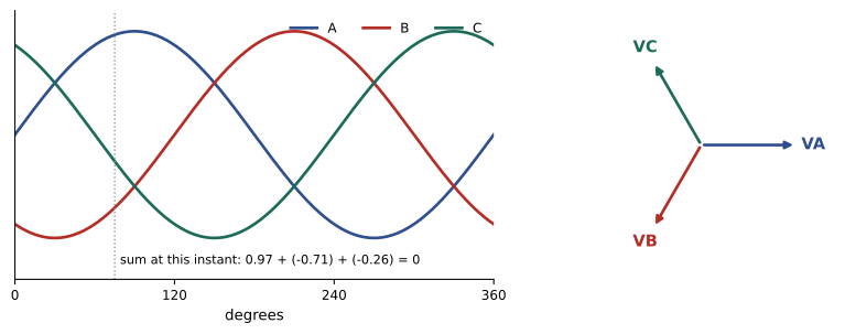
Three-phase power has two major advantages:
- Constant power: in a balanced three-phase load, the total instantaneous power is constant, not pulsating at twice the line frequency as in single-phase circuits. Motors run smoothly with less vibration.
- Conductor economy: transmitting a given power at a given line voltage with three conductors uses about 75% of the copper needed by a single-phase two-wire system.
- Rotating field: three-phase currents in windings spaced 120° apart create a magnetic field that rotates at constant speed, which drives induction and synchronous motors (ELEC-310).
Wye and delta connections
The three windings of a source or the three branches of a load can be connected in two ways.
Wye (star)
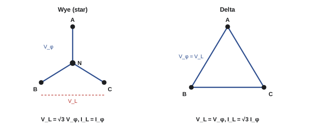
In a wye connection, one end of each winding is joined at a common point, the neutral, and the other ends connect to the lines. Each line carries the current of its own phase winding, so line current equals phase current. The voltage between two lines is the phasor difference of two phase voltages 120° apart, which is \(\sqrt3\) times the phase (line-to-neutral) voltage:
A wye system with its neutral brought out provides two voltages: line-to-line for three-phase loads such as motors and line-to-neutral for single-phase loads such as lighting and receptacles. The neutral is normally grounded at the service.
Delta
In a delta connection, the three windings are connected end to end in a closed loop, and the lines connect to the three junctions. Each winding is connected directly between two lines, so line voltage equals phase voltage. Each line current is the phasor difference of two winding currents, which is \(\sqrt3\) times the winding current:
A delta system has no neutral, unless one winding is centre-tapped to provide one (the high-leg delta below).
Worked problem
Wye-connected heater
Three 10 Ω heating elements are connected in wye to a 600 V three-phase supply. Find the voltage across each element, the line current and the total power.
Show solution
- Phase voltage: \(600/\sqrt3 = 346\) V (nominally 347 V).
- Element current = line current: \(346/10 = 34.6\) A.
- Power: \(3 \times 346 \times 34.6 = 35.9\) kW.
Answer: About 346 V per element, 34.6 A per line and 36 kW total. Reconnecting the same elements in delta would put 600 V across each, tripling the power to 108 kW, which is how dual-rated heaters and motors are reconnected for different voltages.
Standard North American systems
Common Canadian three-phase systems are:
| System | Connection | Typical use |
|---|---|---|
| 347/600 V, 4-wire | Wye, grounded neutral | Commercial and industrial: 600 V motors, 347 V lighting |
| 120/208 V, 4-wire | Wye, grounded neutral | Commercial buildings, apartments: 120 V receptacles, 208 V equipment |
| 600 V, 3-wire | Delta or ungrounded/impedance-grounded wye | Industrial plants with motor loads |
| 120/240 V, 4-wire high-leg delta | Delta with one winding centre-tapped | Older commercial and rural services |
| Medium voltage (4.16 to 34.5 kV) | Wye or delta | Large facilities, utility distribution |
In a 120/240 V high-leg delta system, one transformer winding is centre-tapped and grounded, giving 120 V from each of two lines to neutral. The third line, the high leg, measures about 208 V to neutral (\(240 \times \sqrt3/2\)), which will destroy 120 V equipment connected to it. Codes require the high leg to be identified by orange marking and placed in a specific position in panelboards.
Worked problem
Line-to-neutral voltages
Measure the expected readings between each pair of conductors in a 120/208 V wye panel and in a 120/240 V high-leg delta panel.
Show solution
- 120/208 V wye: any line to neutral 120 V; any line to line \(120 \times \sqrt3 = 208\) V.
- High-leg delta: line to line 240 V for every pair; A and C to neutral 120 V; B (high leg) to neutral \(\sqrt{240^2 - 120^2} = 208\) V.
Answer: In the wye panel, all line-to-neutral readings are equal; in the high-leg delta, one is 208 V. Always verify voltages before connecting single-phase loads in an unfamiliar panel.
Three-phase power
The total power of a balanced three-phase load is three times the power per phase. Expressed in line quantities, which is what meters measure, the result is the same for wye and delta:
where \(V_L\) and \(I_L\) are line voltage and line current and \(\cos\theta\) is the power factor of each phase. Rearranged, the line current of a three-phase load is \(I_L = P/(\sqrt3\,V_L\cos\theta)\), or, for a motor rated in horsepower, \(I_L = (\mathrm{hp} \times 746)/(\sqrt3\,V_L \times \eta \times \mathrm{PF})\), where \(\eta\) is the efficiency. Code tables of full-load motor currents should be used for conductor and protection sizing rather than calculated values (ELEC-220).
Worked problem
Motor line current
A 50 hp, 575 V three-phase motor (on a 600 V system) has an efficiency of 93% and a power factor of 0.87 at full load. Calculate its full-load current.
Show solution
- Output: \(50 \times 746 = 37{,}300\) W; input \(37{,}300/0.93 = 40{,}108\) W.
- \(I_L = 40{,}108/(\sqrt3 \times 575 \times 0.87) = 46.3\) A.
Answer: About 46 A. The CEC table value for a 50 hp, 575 V motor is 52 A, slightly higher to cover typical motors, and the table value is used for sizing.
Unbalanced loads and neutral current
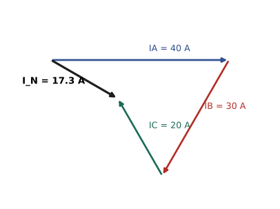
In a four-wire wye system, single-phase loads connected line to neutral are rarely perfectly balanced. The neutral carries the phasor sum of the three line currents. For loads at unity power factor with currents \(I_A\), \(I_B\) and \(I_C\):
If the loads are balanced, \(I_N = 0\); if only one phase is loaded, the neutral carries the full phase current. With linear loads, the neutral current never exceeds the largest line current.
Worked problem
Neutral current
A 120/208 V panel has resistive lighting loads of 40 A on phase A, 30 A on phase B and 20 A on phase C. What is the neutral current?
Show solution
- \(I_N = \sqrt{40^2 + 30^2 + 20^2 - 40 \times 30 - 30 \times 20 - 20 \times 40} = \sqrt{1600 + 900 + 400 - 1200 - 600 - 800} = \sqrt{300} = 17.3\) A.
Answer: 17.3 A, much less than the 90 A that the three phases carry together, because the phase currents largely cancel. Balancing single-phase loads across phases reduces neutral current and voltage drop.
Triplen harmonics in the neutral
Nonlinear single-phase loads, such as computers, LED drivers and electronic ballasts, draw currents rich in the 3rd harmonic (180 Hz) and other odd multiples of three ("triplen" harmonics: 3rd, 9th, 15th). The fundamental currents of the three phases are 120° apart and cancel in the neutral, but the 3rd harmonics of the three phases are in phase with each other (because 3 × 120° = 360°), so they add. With heavy electronic loads, the neutral current can exceed the phase currents, up to about 1.73 times in extreme cases. This overheats neutrals and transformer windings, which is why codes treat the neutral as a current-carrying conductor in such circuits, and why oversized neutrals and K-rated transformers are used in data centres and offices.
Worked problem
Neutral current from triplen harmonics
Each phase of a 120/208 V panel serving computers carries 50 A RMS, consisting of 40 A at 60 Hz and 30 A of 3rd harmonic (\(\sqrt{40^2 + 30^2} = 50\)). The loads are balanced. What is the neutral current?
Show solution
- Fundamental components cancel: 0 A at 60 Hz.
- Third-harmonic components add: \(3 \times 30 = 90\) A at 180 Hz.
Answer: 90 A in the neutral, 1.8 times the phase current, even though the load is perfectly balanced. A neutral sized like the phase conductors would overheat. (The extreme figure here reflects a very distorted current; typical office loads give neutrals of 1.2 to 1.5 times phase current.)
Phase sequence
The order in which the three phases reach their peaks, A-B-C or A-C-B, is the phase sequence or rotation. It determines the direction in which three-phase motors turn: swapping any two lines reverses the motor. Phase sequence must be checked with a phase rotation tester before connecting motors that must turn in one direction (pumps, compressors, conveyors, fans), before paralleling sources, and when connecting a generator or new service. Codes and standards often specify a phase arrangement in panelboards (A, B, C from left to right, top to bottom or front to back), but the actual rotation must still be verified.
Voltage unbalance and single-phasing
Three-phase motors are sensitive to unequal line voltages, which create negative-sequence currents that heat the rotor. Voltage unbalance is commonly defined as
A small voltage unbalance causes a much larger current unbalance, typically 6 to 10 times as large in percentage terms. Motor standards recommend derating motors when voltage unbalance exceeds 1%, and operation above 5% is not recommended. Common causes are large single-phase loads on one phase, a failed capacitor in a power factor bank, or a high-resistance connection in one line.
The extreme case is single-phasing: loss of one line, from a blown fuse, a broken conductor or a failed contact. A running motor continues to turn on two lines but draws greatly increased current in them and overheats rapidly; a stopped motor will not start and draws locked-rotor current. Properly set overload relays in all three lines, or phase-loss monitors, protect against it.
Worked problem
Voltage unbalance
Line voltages measured at a motor are 598 V, 590 V and 575 V. Calculate the voltage unbalance.
Show solution
- Average: \((598 + 590 + 575)/3 = 587.7\) V.
- Maximum deviation: \(587.7 - 575 = 12.7\) V.
- Unbalance: \(12.7/587.7 \times 100 = 2.2\%\).
Answer: About 2.2%, enough to cause current unbalance of perhaps 13 to 20% and noticeable extra heating. The motor should be derated or, better, the cause of the unbalance found and corrected.
Lesson 7 examines neutrals and system grounding in more depth, and Lesson 9 applies three-phase relationships to transformer banks.
Common mistakes
MistakeForgetting the √3 in three-phase power calculations.
InsteadP = √3 V_L I_L cos θ with line values.
MistakeConnecting 120 V loads to the high leg of a 120/240 V delta.
InsteadThe high leg is about 208 V to neutral; identify it (orange) and verify before connecting.
MistakeAssuming a balanced panel has no neutral current.
InsteadTriplen harmonics from electronic loads add in the neutral and can exceed phase current.
MistakeConnecting three-phase motors without checking rotation.
InsteadVerify phase sequence with a rotation tester; swap two lines to reverse.
MistakeIgnoring a few percent of voltage unbalance.
InsteadCurrent unbalance is 6 to 10 times larger; derate or correct the cause.
Summary and key terms
- Three-phase voltages are three equal sine waves 120° apart; balanced currents sum to zero.
- Three-phase delivers constant power, saves conductor material and produces a rotating field.
- Wye: V_L = √3 V_φ, I_L = I_φ; provides line-to-neutral and line-to-line voltages.
- Delta: V_L = V_φ, I_L = √3 I_φ; no neutral unless centre-tapped.
- Common systems: 347/600 V and 120/208 V wye, 600 V three-wire, 120/240 V high-leg delta.
- P = √3 V_L I_L cos θ for any balanced load.
- Neutral current is the phasor sum of line currents; balancing reduces it.
- Triplen harmonics add in the neutral, which can then exceed phase current.
- Phase sequence sets motor rotation; voltage unbalance and single-phasing overheat motors.
- Three-phase system
- A system of three voltages of equal magnitude displaced 120°.
- Wye connection
- A connection with the three windings joined at a common neutral.
- Delta connection
- A connection with the three windings joined end to end in a loop.
- Line voltage
- Voltage between two line conductors.
- Phase voltage
- Voltage across one winding or load branch.
- Neutral
- The common point of a wye connection, usually grounded.
- High-leg delta
- A delta system with one winding centre-tapped, giving one line about 208 V to neutral.
- Balanced load
- A load with equal impedances in all three phases.
- Triplen harmonics
- Harmonics at multiples of three times the fundamental, which add in the neutral.
- Phase sequence
- The order in which the phases reach their peaks.
- Voltage unbalance
- Maximum deviation from the average line voltage as a percentage of the average.
- Single-phasing
- Loss of one line of a three-phase supply to a motor.
Practice problems
Work each problem on paper first, then reveal the answer to check.
A wye system has 120 V line to neutral. What is the line-to-line voltage?
Show answer
208 V.
A delta load draws 30 A line current. What is the current in each branch?
Show answer
30/√3 = 17.3 A.
What is the line current of a 75 kVA balanced load at 600 V three-phase?
Show answer
75,000/(1.732 × 600) = 72.2 A.
A three-phase load draws 40 A at 208 V and 0.85 PF. Find P.
Show answer
1.732 × 208 × 40 × 0.85 = 12.2 kW.
Phase loads (unity PF) are 50 A, 50 A and 20 A. Find the neutral current.
Show answer
√(2500 + 2500 + 400 − 2500 − 1000 − 1000) = √900 = 30 A.
Why do 3rd-harmonic currents add in the neutral?
Show answer
Shifting by 120° at the fundamental shifts the 3rd harmonic by 360°, so the three phases' 3rd harmonics are in phase.
What is the voltage from the high leg to neutral in a 120/240 V delta?
Show answer
About 208 V.
How do you reverse a three-phase motor?
Show answer
Swap any two line conductors.
Line voltages are 210, 206 and 200 V. What is the unbalance?
Show answer
Average 205.3; max deviation 5.3; 2.6%.
What happens to a running motor that loses one phase?
Show answer
It keeps running on two lines with greatly increased current and overheats unless overload or phase-loss protection trips.
Lesson quiz · 5 questions
Score 60% or more to complete this lesson.
Create a free account to save your progress, take quizzes and earn a certificate.