
ELEC-210 · Lesson 4 of 12 · 33 min
Power factor and correction
In a DC circuit, power is simply voltage times current. In an AC circuit with inductance or capacitance, it is not: a motor drawing 50 A at 600 V or 480 V may be doing much less useful work than the product of those numbers suggests, because part of its current is spent building and collapsing magnetic fields rather than delivering energy. That part of the current still heats conductors, loads transformers and causes voltage drop, and utilities often charge for it. Power factor measures how effectively a load uses current. This lesson explains real, reactive and apparent power, the power triangle and power factor, why low power factor costs money, how to calculate and install power factor correction capacitors, and the code rules and pitfalls that go with them.
Power in AC circuits
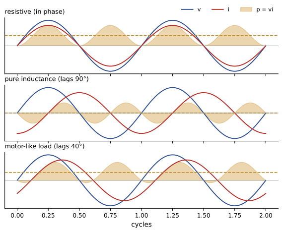
Instantaneous power is the product of instantaneous voltage and current, \(p = vi\). In a resistor, voltage and current are in phase and \(p\) is always positive. In a pure inductor or capacitor, current is 90° out of phase with voltage, so \(p\) is positive for a quarter cycle (energy flowing into the magnetic or electric field) and negative for the next quarter (energy flowing back to the source); the average is zero. Energy sloshes back and forth but none is consumed. In a real load with both resistance and reactance, the average power is
where \(V\) and \(I\) are RMS values and \(\theta\) is the phase angle between them.
Real, reactive and apparent power
Three quantities describe power in AC circuits:
- Real (active) power \(P\), in watts (W): the average power actually converted to heat, light or mechanical work, \(P = VI\cos\theta\). Energy meters measure real energy in kWh.
- Reactive power \(Q\), in volt-amperes reactive (var): the power that oscillates between the source and the magnetic or electric fields, \(Q = VI\sin\theta\). Inductive loads absorb reactive power (lagging); capacitors supply it (leading).
- Apparent power \(S\), in volt-amperes (VA): the product of RMS voltage and current, \(S = VI\). It determines the current, and therefore the heating, voltage drop and size of conductors, transformers, generators and switchgear, which is why transformers and UPSs are rated in kVA.
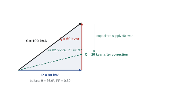
They form the power triangle:
Power factor (PF) is the ratio of real to apparent power. It is 1.0 (unity) for a resistive load, and less than 1 when reactive power flows. It is described as lagging for inductive loads and leading for capacitive loads.
Worked problem
Power triangle of a motor
A single-phase motor draws 18 A at 240 V with a power factor of 0.75 lagging. Find the apparent, real and reactive power.
Show solution
- \(S = 240 \times 18 = 4320\) VA.
- \(P = 4320 \times 0.75 = 3240\) W.
- \(\theta = \cos^{-1}0.75 = 41.4°\); \(Q = 4320 \sin 41.4° = 2857\) var (or \(\sqrt{4320^2 - 3240^2}\)).
Answer: 4.32 kVA, 3.24 kW and 2.86 kvar lagging. The supply must carry 18 A even though only 75% of the volt-amperes do useful work.
Typical power factors
| Load | Typical power factor |
|---|---|
| Resistance heating, incandescent lamps | 1.0 |
| Induction motor, full load | 0.80 to 0.90 lagging |
| Induction motor, half load | 0.65 to 0.80 lagging |
| Induction motor, no load | 0.10 to 0.30 lagging |
| Welding transformers | 0.5 to 0.7 lagging |
| Magnetic-ballast fluorescent (uncorrected) | 0.5 to 0.6 lagging |
| Modern LED drivers, IT power supplies with PFC | 0.90 to 0.99 |
| Variable frequency drives (displacement PF) | 0.95 or higher |
Lightly loaded induction motors are the most common cause of poor power factor in industry: the magnetizing current needed to establish the motor's field is nearly the same at all loads, so at light load it forms most of the current. Oversized motors running well below their rating therefore have poor power factor as well as reduced efficiency.
Why low power factor matters
For a given real power, current is inversely proportional to power factor: \(I = P/(V \times \mathrm{PF})\). Low power factor therefore means:
- Higher current, requiring larger conductors, switchgear and transformers for the same useful load.
- Higher \(I^2R\) losses in conductors and transformers, which grow with the square of current.
- Greater voltage drop along feeders, which can cause equipment to malfunction.
- Less spare capacity: a transformer rated 500 kVA can supply 500 kW at unity power factor but only 350 kW at 0.7.
- Utility charges for poor power factor.
Canadian utilities recover the cost of supplying reactive power in several ways. Many bill demand in kVA rather than kW for larger customers, or bill demand at the greater of the measured kW and a percentage (often 90%) of the measured kVA, so that customers with a power factor below about 0.9 pay for more demand than they use. Others apply explicit power factor penalties. The details are set out in each utility's rate schedules.
Worked problem
Demand charges at low power factor
A plant has a peak demand of 400 kW at 0.72 power factor. Its utility bills demand at the greater of the measured kW and 90% of the measured kVA, at $14 per kW per month. What is the monthly demand charge, and what would it be at 0.95 power factor?
Show solution
- At 0.72: kVA = 400/0.72 = 556; 90% of that is 500 kW, greater than 400, so billed demand is 500 kW: \(500 \times 14 = \$7000\).
- At 0.95: kVA = 421; 90% is 379 kW, less than 400, so billed demand is 400 kW: \$5600.
Answer: A saving of $1400 a month, $16,800 a year, before counting reduced losses. Capacitors to correct a 400 kW load from 0.72 to 0.95 (about 250 kvar, as calculated below) typically cost a fraction of that, so power factor correction often pays back in one to three years.
Power factor correction
Since inductive loads absorb reactive power and capacitors supply it, capacitors connected in parallel with an inductive load can supply its reactive power locally, so that it no longer flows from the utility through the service, feeders and transformers. The real power is unchanged; the apparent power and current fall. The capacitor rating needed to raise the power factor from \(\mathrm{PF}_1\) to \(\mathrm{PF}_2\) at real power \(P\) is
Worked problem
Sizing a capacitor bank
A 400 kW load has a power factor of 0.72 lagging. What capacitor rating raises it to 0.95? How much does the apparent power fall?
Show solution
- \(\theta_1 = \cos^{-1}0.72 = 43.9°\), \(\tan\theta_1 = 0.964\). \(\theta_2 = \cos^{-1}0.95 = 18.2°\), \(\tan\theta_2 = 0.329\).
- \(Q_C = 400 \times (0.964 - 0.329) = 254\) kvar.
- Apparent power: before \(400/0.72 = 556\) kVA; after \(400/0.95 = 421\) kVA.
Answer: About 254 kvar, commonly supplied as a 250 kvar bank, reducing apparent power by 24%. Current and the \(I^2R\) losses in the supply fall by 24% and 42% respectively.
Worked problem
Current reduction on a feeder
The 400 kW load above is supplied at 600 V three-phase. Find the line current before and after correction.
Show solution
- Three-phase current: \(I = S/(\sqrt3 V)\) (Lesson 6).
- Before: \(556{,}000/(1.732 \times 600) = 535\) A. After: \(421{,}000/(1.732 \times 600) = 405\) A.
Answer: The current falls from 535 A to 405 A, freeing 130 A of capacity on the feeder and transformer for additional load.
Where to install capacitors
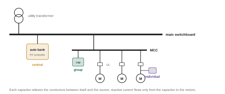
- At individual motors: the capacitor is connected at the motor terminals and switched with it, so reactive power is supplied right where it is consumed, relieving the branch circuit and feeder as well as the service. Simple, but many small capacitors are needed.
- Group correction: a capacitor bank on a motor control centre or distribution panel serving several motors.
- Central automatic correction: a bank at the main switchboard with a controller that switches capacitor steps in and out to track the load, keeping power factor near a target without overcorrecting at light load. This is the most common approach in larger facilities, though it does not relieve the feeders downstream.
Overcorrection, making the load leading, is undesirable: it raises voltage, can still incur utility charges, and wastes capacitors. Fixed capacitors sized for full load can overcorrect when the load is light, which is why automatic banks are used where load varies.
Code requirements for capacitors
The Canadian Electrical Code (Section 26) sets requirements for capacitor installations, including:
- Conductors supplying a capacitor must have an ampacity of at least 135% of the capacitor's rated current, because capacitor current rises with voltage and harmonics and capacitors are manufactured with a positive tolerance.
- Overcurrent protection and a means of disconnection for each capacitor bank, unless the capacitor is connected on the load side of a motor's overload device and switched with the motor.
- Means to discharge the stored energy automatically to a safe voltage within a short time after disconnection.
- Where capacitors are connected at a motor on the load side of its overload device, the overload setting must be based on the reduced line current, and the capacitor must not exceed the value that would cause the motor to self-excite when disconnected.
Worked problem
Conductor for a capacitor
A 50 kvar, 600 V, three-phase capacitor is installed. What is its rated current, and what minimum conductor ampacity is required?
Show solution
- Rated current: \(50{,}000/(1.732 \times 600) = 48.1\) A.
- Minimum ampacity: \(1.35 \times 48.1 = 65\) A.
Answer: About 48 A rated, requiring conductors with an ampacity of at least 65 A.
Pitfalls
- Self-excitation: a capacitor at a motor's terminals that supplies more than the motor's no-load magnetizing reactive power can keep the motor generating voltage after it is disconnected while it coasts, producing overvoltages and dangerous reclosing transients. Motor manufacturers publish maximum capacitor ratings for each motor.
- Harmonic resonance: capacitors and the system inductance form a resonant circuit (Lesson 2). Where variable frequency drives and other nonlinear loads produce harmonics, a capacitor bank can amplify them, overheating the capacitors and distorting the voltage. Detuned banks with series reactors, or active harmonic filters, are used instead.
- Switching transients: energizing a capacitor bank causes a brief inrush and voltage transient that can trip drives. Automatic banks use soft-switching contactors or thyristor switching to reduce this.
- True versus displacement power factor: with harmonics present, the true power factor (\(P/S\) with all currents included) is lower than the displacement power factor (the cosine of the angle between the fundamental voltage and current). Capacitors correct only the displacement part; harmonic currents need filters. A power quality analyzer measures both.
- Capacitor failure: capacitors age, especially when hot or subjected to harmonics, and lose capacitance. Automatic banks should be inspected and their step currents measured periodically.
Lesson 5 shows how power, energy, demand and power factor are measured in the field, and Lesson 3 explains why capacitor banks in buildings with drives often need reactors.
Common mistakes
MistakeMultiplying volts by amps to get watts in an AC circuit with motors.
InsteadV × I gives volt-amperes; real power is V × I × PF.
MistakeSizing capacitors to reach unity power factor at full load with fixed banks.
InsteadFixed banks overcorrect at light load; target about 0.95 and use automatic switching where loads vary.
MistakeInstalling capacitor banks in plants with many drives without a harmonic check.
InsteadCheck for resonance; use detuned banks or filters.
MistakeSizing capacitor conductors at 100% of rated current.
InsteadConductors must have at least 135% of the capacitor's rated current.
MistakeLeaving motor overloads set for uncorrected current when capacitors are added at the motor.
InsteadReset overloads for the reduced line current.
Summary and key terms
- With phase shift, average power is P = VI cos θ; reactive energy oscillates without being consumed.
- Real power P (W), reactive power Q (var) and apparent power S (VA) form the power triangle: S² = P² + Q².
- Power factor = P/S = cos θ; lagging for inductive loads, leading for capacitive.
- Lightly loaded induction motors are the main cause of poor power factor.
- Low PF increases current, losses, voltage drop and utility charges and reduces capacity.
- Correction capacitors supply reactive power locally: Q_C = P(tan θ₁ − tan θ₂).
- Capacitors may be installed at motors, in groups or centrally with automatic switching.
- CEC Section 26: 135% conductor ampacity, overcurrent protection, disconnection and discharge.
- Watch for self-excitation, harmonic resonance, switching transients and true versus displacement PF.
- Real power
- Average power converted to work or heat, in watts.
- Reactive power
- Power oscillating between source and fields, in vars.
- Apparent power
- The product of RMS voltage and current, in volt-amperes.
- Power triangle
- The right triangle relating P, Q and S.
- Power factor
- The ratio of real power to apparent power, cos θ for sine waves.
- Lagging power factor
- Power factor of an inductive load, where current lags voltage.
- Leading power factor
- Power factor of a capacitive load, where current leads voltage.
- Power factor correction
- Adding capacitors to supply reactive power locally.
- kvar
- Kilovolt-ampere reactive, the unit of capacitor rating.
- Automatic capacitor bank
- A bank whose steps are switched by a controller to follow the load.
- Self-excitation
- A disconnected motor generating voltage sustained by its terminal capacitors.
- Displacement power factor
- The cosine of the angle between fundamental voltage and current.
- True power factor
- P/S including the effect of harmonics.
Practice problems
Work each problem on paper first, then reveal the answer to check.
A load draws 25 A at 120 V and 2400 W. What is its power factor?
Show answer
S = 3000 VA; PF = 0.8.
For S = 50 kVA and P = 40 kW, find Q.
Show answer
30 kvar.
A 75 kW load at 0.8 PF: find S and Q.
Show answer
S = 93.75 kVA; Q = 56.25 kvar.
Why does a lightly loaded induction motor have a low power factor?
Show answer
Its magnetizing (reactive) current stays nearly constant while its real-power current falls.
How many kW can a 300 kVA transformer supply at 0.75 PF?
Show answer
225 kW.
What capacitor rating raises a 200 kW load from 0.8 to 0.95 PF?
Show answer
200 × (0.750 − 0.329) = 84 kvar.
By what fraction do I²R losses fall when PF improves from 0.75 to 0.95 at constant kW?
Show answer
Current ratio 0.75/0.95 = 0.789; losses × 0.623, a 38% reduction.
A 30 kvar, 600 V, three-phase capacitor: rated current and minimum conductor ampacity?
Show answer
28.9 A; 39 A.
What is self-excitation and how is it avoided?
Show answer
A coasting disconnected motor kept energized by its capacitors; keep capacitor kvar below the motor's no-load magnetizing kvar.
Why do capacitors not correct the true power factor of a load with heavy harmonics?
Show answer
They correct only displacement PF; harmonic currents add to RMS current and need filters.
Lesson quiz · 5 questions
Score 60% or more to complete this lesson.
Create a free account to save your progress, take quizzes and earn a certificate.