
ELEC-210 · Lesson 2 of 12 · 39 min
Inductance and capacitance
Resistance is not the only thing that opposes current in an AC circuit. Every coil, from a contactor coil to a motor winding or a transformer, has inductance, which opposes changes in current by storing energy in a magnetic field. Every pair of conductors separated by insulation, from a power factor capacitor to a long cable, has capacitance, which opposes changes in voltage by storing energy in an electric field. In AC circuits, where current and voltage change continuously, these effects produce reactance, an opposition to current that depends on frequency, and shift the phase of current relative to voltage. Understanding them explains why a contactor coil burns out on DC, why capacitors can be deadly after the power is off, why motors have poor power factor, and how filters and power factor correction work.
Inductance
A current in a conductor produces a magnetic field around it, and winding the conductor into a coil concentrates the field, especially with an iron core. When the current changes, the changing magnetic field induces a voltage in the coil itself (self-induction). By Lenz's law, the induced voltage opposes the change that causes it: it resists a rising current and tries to maintain a falling one. The property is inductance \(L\), measured in henries (H):
A coil has an inductance of 1 H if a current changing at 1 A/s induces 1 V. Inductance increases with the number of turns (as the square), the cross-sectional area of the coil, and the permeability of the core, which is why iron-cored coils have far more inductance than air-cored ones of the same size. Practical values range from microhenries in electronic circuits to several henries in the coils of large relays and contactors.
Inductive kick
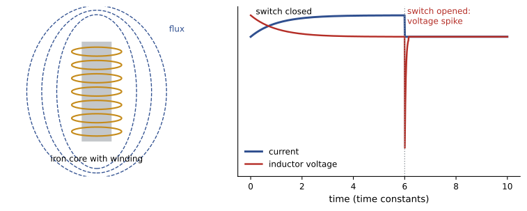
Because an inductor resists changes in current, interrupting the current suddenly, by opening a switch or contact, produces a very large induced voltage as the magnetic field collapses. This inductive kick can reach thousands of volts across the opening contacts, causing arcing, pitting and damage to electronic switches. It is why relay and contactor coils driven by electronic outputs need suppression: a diode across DC coils, or an RC snubber or metal-oxide varistor across AC coils. The same principle is used deliberately in vehicle ignition coils and in electric fences.
Energy stored
An inductor carrying current \(I\) stores energy in its magnetic field, \(W = \tfrac12 LI^2\). This energy must go somewhere when the current is interrupted, which is the source of the inductive kick and of the arc when a large motor circuit is opened under load.
Inductive reactance
With AC applied, the current in an inductor changes continuously, so the inductor continuously opposes it. The opposition is the inductive reactance \(X_L\), in ohms:
Reactance is proportional to frequency: the faster the current changes, the more an inductor opposes it. At DC (\(f = 0\)), an ideal inductor has zero reactance and only its winding resistance limits current. In a purely inductive circuit, \(I = V/X_L\), and the current lags the voltage by exactly 90°, because the induced voltage is greatest when the current is changing fastest, which is as the current passes through zero.
Worked problem
A contactor coil on AC and DC
A 120 V, 60 Hz contactor coil has an inductance of 1.5 H (with the armature closed) and a resistance of 40 Ω. Estimate its current on 120 V AC, and on 120 V DC.
Show solution
- \(X_L = 2\pi \times 60 \times 1.5 = 565\) Ω.
- On AC, the coil's impedance is \(Z = \sqrt{40^2 + 565^2} = 566\) Ω, so \(I = 120/566 = 0.21\) A.
- On DC, only resistance limits current: \(I = 120/40 = 3.0\) A.
Answer: About 0.21 A on AC but 3.0 A on DC, 14 times as much, dissipating \(3^2 \times 40 = 360\) W in a coil designed for a few watts. An AC coil connected to DC burns out quickly. Similarly, an AC coil whose armature cannot close (stuck by debris) has much lower inductance, draws high current and overheats.
Worked problem
A reactor at a different frequency
A line reactor rated 3 mH is installed ahead of a variable frequency drive. What is its reactance at 60 Hz? At the 5th harmonic (300 Hz)?
Show solution
- 60 Hz: \(2\pi \times 60 \times 0.003 = 1.13\) Ω.
- 300 Hz: \(2\pi \times 300 \times 0.003 = 5.65\) Ω.
Answer: 1.13 Ω at 60 Hz and 5.65 Ω at 300 Hz. Because reactance rises with frequency, the reactor opposes harmonic currents much more strongly than the fundamental, which is why line reactors reduce the harmonic currents drawn by drives.
Resistance and inductance in series
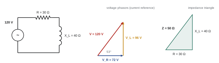
Real coils have both resistance and inductance, and many circuits, such as a motor or a fluorescent ballast with a lamp, behave as a resistance in series with an inductance. The same current flows through both; the voltage across the resistance is in phase with the current, while the voltage across the inductance leads the current by 90°. The source voltage is the phasor sum, so the voltages do not add arithmetically. The total opposition is the impedance \(Z\):
The relationship forms an impedance triangle with \(R\) along the base, \(X_L\) vertical and \(Z\) as the hypotenuse; the angle \(\theta\) is the angle by which the current lags the source voltage.
Worked problem
A series RL circuit
A 120 V, 60 Hz supply feeds a coil with 30 Ω resistance and 40 Ω inductive reactance. Find the impedance, current, phase angle and the voltage across each component.
Show solution
- \(Z = \sqrt{30^2 + 40^2} = 50\) Ω; \(I = 120/50 = 2.4\) A.
- \(\theta = \tan^{-1}(40/30) = 53.1°\); current lags.
- \(V_R = 2.4 \times 30 = 72\) V; \(V_L = 2.4 \times 40 = 96\) V.
Answer: Z = 50 Ω, I = 2.4 A lagging by 53°, V_R = 72 V and V_L = 96 V. The component voltages add to 168 V arithmetically, more than the 120 V supply, but as phasors \(\sqrt{72^2 + 96^2} = 120\) V. A voltmeter across each component confirms this, a common surprise for apprentices.
Capacitance
A capacitor consists of two conductive plates separated by an insulator, the dielectric. When a voltage is applied, charge accumulates on the plates, positive on one and negative on the other, creating an electric field in the dielectric that stores energy. Capacitance \(C\), in farads (F), is the charge stored per volt, \(C = Q/V\). It increases with plate area and the permittivity of the dielectric, and decreases with the separation between plates. A farad is very large; practical capacitors are rated in microfarads (µF), nanofarads (nF) and picofarads (pF), although supercapacitors reach thousands of farads.
The current into a capacitor is proportional to the rate of change of its voltage:
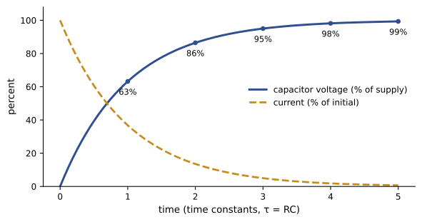
A capacitor therefore opposes changes in voltage: its voltage cannot change instantly, and a sudden change would require an infinite current. When connected to DC through a resistance, it charges along an exponential curve with time constant \(\tau = RC\), reaching 63% of the supply voltage in one time constant and practically full charge (over 99%) in five. Once charged, it blocks DC entirely.
Capacitor safety
A charged capacitor stores energy \(W = \tfrac12 CV^2\) and keeps it after the supply is disconnected. Power factor correction capacitors, variable frequency drive DC buses, UPS systems, motor run capacitors and even long cables can hold lethal charges for minutes. Large capacitors have built-in discharge resistors, and codes require capacitors to be discharged to a safe level within a specified time after disconnection, but resistors can fail open. Before working on such equipment, wait the time stated on the equipment label, then verify zero voltage with a meter at the capacitor terminals, and discharge with an approved discharge tool if required.
Worked problem
Energy in a drive's DC bus
A 600 V variable frequency drive has a DC bus of about 850 V with 4700 µF of capacitance. How much energy is stored? Its discharge resistor is 100 kΩ. How long until the voltage falls below 50 V?
Show solution
- Energy: \(\tfrac12 \times 0.0047 \times 850^2 = 1698\) J.
- Time constant: \(\tau = RC = 100{,}000 \times 0.0047 = 470\) s.
- Discharge: \(v = 850e^{-t/470}\); for 50 V, \(t = 470\ln(850/50) = 470 \times 2.83 = 1332\) s, about 22 minutes.
Answer: About 1.7 kJ, enough to be lethal, and over 20 minutes to bleed down through this resistor. Manufacturers state the waiting time on the drive, but the voltage must still be verified before touching the bus.
Capacitive reactance
With AC applied, a capacitor charges and discharges every half cycle, so alternating current flows in the circuit even though no charge passes through the dielectric. The opposition is the capacitive reactance:
Capacitive reactance falls as frequency rises: capacitors pass high frequencies easily and block DC. In a purely capacitive circuit the current leads the voltage by 90°, because the current is greatest when the voltage is changing fastest. A memory aid is ELI the ICE man: in an inductive circuit (L), voltage (E) comes before current (I); in a capacitive circuit (C), current comes before voltage.
Worked problem
A motor run capacitor
A single-phase motor uses a 30 µF run capacitor on 240 V, 60 Hz. What is its reactance, and roughly what current flows through it if 330 V appears across it?
Show solution
- \(X_C = 1/(2\pi \times 60 \times 30 \times 10^{-6}) = 88.4\) Ω.
- \(I = 330/88.4 = 3.7\) A.
Answer: About 88 Ω and 3.7 A. The voltage across a run capacitor can exceed the supply voltage because of the phase relationships in the auxiliary winding circuit, which is why run capacitors are rated 370 V or 440 V for 240 V motors. Replacements must match both the capacitance and the voltage rating.
Resistance and capacitance; series RLC circuits
In a series RC circuit, the impedance is \(Z = \sqrt{R^2 + X_C^2}\) and the current leads the voltage by \(\tan^{-1}(X_C/R)\). With resistance, inductance and capacitance in series, the inductive and capacitive voltages are 180° apart and partly cancel, so the net reactance is their difference:
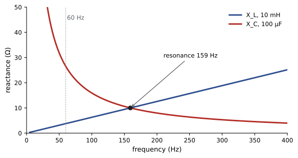
If \(X_L > X_C\) the circuit is inductive and current lags; if \(X_C > X_L\) it is capacitive and current leads. When \(X_L = X_C\), the reactances cancel, the impedance equals \(R\), and the current is at its maximum; this is series resonance, at \(f_r = 1/(2\pi\sqrt{LC})\). At resonance the voltages across the inductor and capacitor individually can be many times the supply voltage. In power systems, resonance between power factor capacitors and the system inductance at a harmonic frequency can amplify harmonic voltages and currents and damage capacitors, which is why harmonic studies and detuned capacitor banks (capacitors with series reactors) are used where drives are common.
Worked problem
Resonant frequency
A capacitor bank effectively forms a resonant circuit with the supply transformer. The equivalent inductance is 0.5 mH and the capacitance is 1400 µF. At what frequency does it resonate, and which harmonic is that close to?
Show solution
- \(f_r = 1/(2\pi\sqrt{0.0005 \times 0.0014}) = 1/(2\pi \times 8.37 \times 10^{-4}) = 190\) Hz.
Answer: About 190 Hz, close to the 3rd harmonic (180 Hz). Any 3rd-harmonic current from loads could excite this resonance; a detuning reactor that moves the resonance below the 5th harmonic, typically to around 4.2 times the fundamental (250 Hz), is standard practice where 5th and 7th harmonics dominate.
Parallel circuits
In parallel circuits the voltage is common and the branch currents add as phasors. A resistive branch draws current in phase with the voltage, an inductive branch draws current lagging by 90°, and a capacitive branch draws current leading by 90°. The total current is \(I = \sqrt{I_R^2 + (I_L - I_C)^2}\). This is the basis of power factor correction: a capacitor in parallel with an inductive load supplies current that cancels part of the load's lagging current, reducing the total current drawn from the supply (Lesson 4).
Worked problem
Parallel RL and C
A 240 V supply feeds, in parallel, a resistive heater drawing 10 A, a coil drawing 8 A (purely inductive) and a capacitor drawing 5 A. What is the total current?
Show solution
- \(I = \sqrt{10^2 + (8 - 5)^2} = \sqrt{109} = 10.4\) A.
Answer: 10.4 A, far less than the arithmetic sum of 23 A. Without the capacitor, the total would be \(\sqrt{10^2 + 8^2} = 12.8\) A. Clamp meter readings on each branch and on the feeder confirm phasor addition in practice.
Lesson 3 shows what happens when inductive and capacitive reactances cancel at resonance, and how harmonics interact with the capacitors and inductances in a building.
Common mistakes
MistakeConnecting an AC coil to DC of the same voltage.
InsteadWithout reactance, DC current is limited only by resistance and the coil burns out.
MistakeOpening an inductive circuit with no suppression on electronic outputs.
InsteadUse a diode, RC snubber or MOV across coils to absorb the inductive kick.
MistakeAssuming a capacitor is safe once power is off.
InsteadWait the labelled time, then verify zero voltage at the capacitor terminals.
MistakeAdding component voltages arithmetically in RL or RC circuits.
InsteadThey add as phasors; individual voltages can exceed the supply.
MistakeReplacing a run capacitor with one of lower voltage rating.
InsteadMatch both capacitance and voltage rating; capacitor voltage can exceed the line voltage.
Summary and key terms
- Inductance opposes changes in current: v = L di/dt; it depends on turns², area and core.
- Interrupting inductive current produces a voltage spike (inductive kick); stored energy ½LI².
- X_L = 2πfL rises with frequency; current lags voltage by 90° in a pure inductor.
- Series RL: Z = √(R² + X_L²), θ = tan⁻¹(X_L/R); voltages add as phasors.
- Capacitance stores charge: i = C dv/dt; time constant τ = RC; five τ for full charge.
- Capacitors store ½CV² and can remain lethal after disconnection.
- X_C = 1/(2πfC) falls with frequency; current leads voltage by 90° (ELI the ICE man).
- Series RLC: Z = √(R² + (X_L − X_C)²); resonance at f_r = 1/(2π√LC) can amplify harmonics.
- Parallel branch currents add as phasors; capacitors offset inductive current.
- Inductance
- The property of a coil that opposes changes in current, measured in henries.
- Lenz's law
- An induced voltage opposes the change that produces it.
- Inductive kick
- The high voltage produced when inductive current is interrupted.
- Inductive reactance
- Opposition of an inductor to AC: X_L = 2πfL.
- Impedance
- Total opposition to AC, combining resistance and reactance.
- Capacitance
- The ability to store charge per volt, measured in farads.
- Dielectric
- The insulating material between capacitor plates.
- Time constant
- For RC circuits, τ = RC; the time to reach 63% of the final change.
- Capacitive reactance
- Opposition of a capacitor to AC: X_C = 1/(2πfC).
- Resonance
- The condition X_L = X_C, giving maximum series current or minimum parallel current.
- Discharge resistor
- A resistor that bleeds stored charge from a capacitor after disconnection.
- Snubber
- A circuit that absorbs voltage spikes across switching contacts or coils.
- Detuned capacitor bank
- Capacitors with series reactors that shift resonance away from harmonics.
Practice problems
Work each problem on paper first, then reveal the answer to check.
What is the reactance of a 0.2 H inductor at 60 Hz?
Show answer
75.4 Ω.
A coil has R = 12 Ω and X_L = 16 Ω on 120 V. Find Z, I and θ.
Show answer
Z = 20 Ω; I = 6 A; θ = 53.1° lagging.
Why do AC contactors draw more current while the armature is pulling in?
Show answer
With the air gap open, inductance and reactance are lower, so current is higher until the armature closes.
What is the reactance of a 50 µF capacitor at 60 Hz?
Show answer
53.1 Ω.
A 100 µF capacitor charges through 10 kΩ. How long to essentially full charge?
Show answer
τ = 1 s; about 5 s.
How much energy does a 50 µF capacitor store at 400 V?
Show answer
½ × 50e-6 × 400² = 4 J.
A circuit has R = 20 Ω, X_L = 50 Ω and X_C = 35 Ω in series. Find Z and whether it is inductive or capacitive.
Show answer
Z = √(400 + 225) = 25 Ω; inductive.
Find the resonant frequency of 10 mH and 100 µF.
Show answer
1/(2π√1e-6) = 159 Hz.
Branch currents are I_R = 6 A, I_L = 10 A, I_C = 2 A in parallel. Total current?
Show answer
√(36 + 64) = 10 A.
State the ELI the ICE man rule.
Show answer
In inductive circuits voltage leads current; in capacitive circuits current leads voltage.
Lesson quiz · 5 questions
Score 60% or more to complete this lesson.
Create a free account to save your progress, take quizzes and earn a certificate.