
ELEC-210 · Lesson 11 of 12 · 32 min
Fault current and equipment ratings
A short circuit can draw tens of thousands of amperes from a building's distribution system, far more than any load. Every circuit breaker, fuse, panelboard and switch that might carry or interrupt that current must be rated for it, or it can explode, start a fire or fail to clear the fault. Fault current also sets the severity of arc flash hazards to workers. Electricians need to estimate available fault current, read and apply equipment ratings, and recognize when a change, such as a larger transformer or a new utility supply, makes existing equipment inadequate. This lesson covers the sources of fault current, calculating it at the transformer and along feeders, the effect of motors, interrupting and short-circuit current ratings, current-limiting devices and series ratings, labelling requirements, and the link to arc flash.
Where fault current comes from
When a bolted short circuit occurs, the current is limited only by the impedance of everything between the sources and the fault: the utility system, transformers, conductors and busway, and the fault itself. The sources include:
- The utility, through the service transformer. The transformer's impedance usually dominates in buildings.
- Motors running at the time of the fault: an induction motor acts briefly as a generator, driven by its own inertia and residual flux, contributing roughly four to six times its full-load current for the first few cycles.
- On-site generators, UPSs and inverter-based sources, each with its own characteristic contribution (inverters typically contribute only 1.1 to 1.5 times rated current, see ELE-380, Lesson 3, for the theory).
Calculations start from the worst case: the maximum utility contribution (often given by the utility as available fault current or MVA at the service, or assumed infinite on the primary for conservatism), all motors running, and a bolted three-phase fault, which usually gives the highest current on solidly grounded low-voltage systems.
Fault current at a transformer secondary
Lesson 8 showed that with an infinite source, the fault current at a transformer's secondary terminals is its full-load current divided by its per-unit impedance:
Transformer impedances on nameplates are subject to manufacturing tolerance (often ±7.5% or ±10%), so conservative calculations reduce the nameplate impedance by the tolerance, raising the fault current. With a finite utility source, the source impedance adds to the transformer impedance and reduces the current.
Worked problem
Fault current at a service transformer
A 1,000 kVA, 600 V (347/600 V) three-phase transformer has 5.75% impedance. Find its full-load current and the available three-phase fault current at its secondary, assuming an infinite source and allowing for a −10% impedance tolerance.
Show solution
- Full-load current: \(1{,}000{,}000/(\sqrt3 \times 600) = 962\) A.
- Effective impedance: \(0.9 \times 5.75 = 5.175\%\).
- Fault current: \(962 \times 100/5.175 = 18{,}600\) A.
Answer: About 18.6 kA (16.7 kA using the nameplate impedance). Equipment at the main switchboard must be rated at least this, and higher if motor contribution is added.
Fault current along a feeder
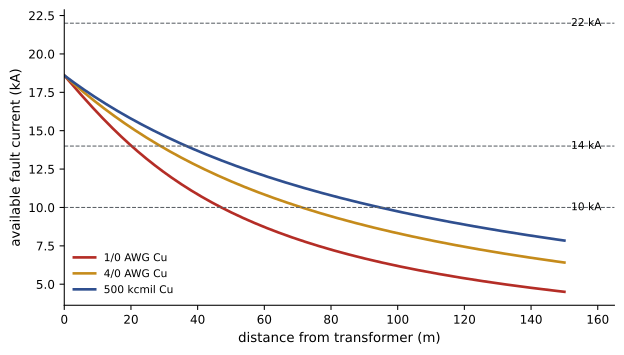
Conductors add impedance between the source and a downstream fault, so fault current falls with distance. A convenient method converts everything to ohms per phase and adds the impedances:
- Source and transformer impedance referred to the secondary: \(Z_T = V_{LL}/(\sqrt3\,I_{sc})\), where \(I_{sc}\) is the fault current at the transformer secondary.
- Feeder impedance: the conductor resistance and reactance per phase for its length (Lesson 10), combined as \(\sqrt{(R_T + R_f)^2 + (X_T + X_f)^2}\), or, as a simpler conservative approximation, by adding magnitudes.
- Fault current at the downstream point: \(I_{sc,2} = V_{LL}/(\sqrt3\,Z_{\text{total}})\).
Manufacturers publish the equivalent point-to-point method, which uses a conductor constant \(C\) for each size and raceway type and computes a multiplier \(M = 1/(1 + f)\) with \(f = \sqrt3\,L\,I_{sc}/(C\,V_{LL})\) for three-phase faults; the two approaches give similar results.
Worked problem
Fault current at a downstream panel
The 18.6 kA switchboard in the previous example feeds a panel 60 m away through 1/0 AWG copper conductors in steel conduit (R = 0.39 Ω/km, X = 0.18 Ω/km). Estimate the fault current at the panel. The transformer X/R ratio is about 5.
Show solution
- Source impedance: \(600/(\sqrt3 \times 18{,}600) = 0.0186\ \Omega\); with X/R = 5: \(R_T = 0.0037\), \(X_T = 0.0183\ \Omega\).
- Feeder: \(R_f = 0.39 \times 0.060 = 0.0234\ \Omega\), \(X_f = 0.18 \times 0.060 = 0.0108\ \Omega\).
- Total: \(\sqrt{0.0271^2 + 0.0291^2} = 0.0398\ \Omega\). Fault current: \(600/(\sqrt3 \times 0.0398) = 8{,}700\) A.
Answer: About 8.7 kA at the panel, less than half the switchboard value. A panel and breakers rated 10 kA would be adequate here (with margin for motor contribution to be checked); the same panel installed close to the transformer would not.
Motor contribution
Running induction motors add their own fault current, which flows from the motor toward the fault. A common estimate is four times the full-load current of all motors that may be running, added to the utility contribution at the point of interest. The contribution decays within a few cycles, so it matters most for the first-cycle (momentary) duty of breakers and for equipment close to large motor groups.
Worked problem
Adding motor contribution
The 600 V switchboard above supplies motors with a total full-load current of 400 A. What is the total available fault current at the switchboard?
Show solution
- Motor contribution: \(4 \times 400 = 1{,}600\) A.
- Total: \(18{,}600 + 1{,}600 = 20{,}200\) A.
Answer: About 20.2 kA. Equipment rated 22 kA would suffice, but 18 kA equipment chosen on the transformer figure alone would not.
Interrupting ratings and short-circuit current ratings
Two kinds of rating apply:
- Interrupting rating (also called interrupting capacity, AIC or kAIC): the highest current at rated voltage that a fuse or circuit breaker can safely interrupt. A breaker rated 10 kA attempting to interrupt 25 kA may fail violently.
- Short-circuit current rating (SCCR) or withstand rating: the fault current that equipment such as panelboards, switchboards, motor controllers, transfer switches and industrial control panels can withstand until the protective device clears the fault, without exceeding damage limits. An assembly's SCCR is limited by its weakest component and the protection ahead of it.
The CEC (Rule 14-012) requires overcurrent devices to have an interrupting rating sufficient for the voltage and the available fault current at the point of installation, and equipment to be suitable for the fault current it may be exposed to. Equipment certification marks list these ratings, and electrical inspection authorities increasingly ask for the available fault current to be documented on drawings or labels.
Typical ratings: residential breakers 10 kA; commercial panelboard breakers 10, 14, 18, 22, 25, 35, 42 or 65 kA, and up to 100 kA or more for high-interrupting types; current-limiting fuses (such as Class J, L, RK1 and T) 200 kA or 300 kA.
Current-limiting devices and series ratings
A current-limiting fuse or breaker opens so fast, within the first half-cycle, that the fault current never reaches its prospective peak. The let-through current and energy (\(I^2t\)) are a small fraction of what the circuit could deliver. Current-limiting fuses can protect downstream equipment with lower withstand ratings, when the combination has been tested.
Series ratings allow a downstream breaker with a lower interrupting rating to be used where available fault current exceeds that rating, provided an upstream fuse or breaker of a tested combination limits the current. Series-rated combinations must be tested and listed together, marked on the equipment, and not used where motors connected between the two devices contribute significant fault current. Changing either device to a different type invalidates the rating.
Worked problem
Applying a series rating
A panelboard has 10 kA branch breakers and is fed by a 200 A main breaker. Available fault current at the panel is 18 kA. The panel label lists a series combination rating of 22 kA with a specific 200 A main breaker type upstream. Is the installation acceptable?
Show solution
- The branch breakers alone (10 kA) are inadequate for 18 kA.
- The listed series combination is rated 22 kA, above the 18 kA available.
Answer: Yes, provided the upstream breaker is exactly the type listed, the combination is marked as required, and no significant motor load is connected between the two devices. If the main breaker is later replaced with a different model, the series rating is lost and the panel may become dangerously underrated.
When fault current changes
Available fault current is not fixed. It rises when:
- The utility replaces the service transformer with a larger or lower-impedance unit, or strengthens its system.
- A building's transformer is replaced or paralleled with another (Lesson 9).
- Feeders are shortened, or conductors enlarged (for voltage drop, Lesson 10).
- On-site generation or large motors are added.
Each such change may leave existing panels and breakers underrated. Good practice, and in many jurisdictions a code or labelling requirement, is to recalculate and update fault current labels when the supply or distribution changes, and to ask the utility for its maximum available fault current when planning new services.
Fault current and arc flash
An arcing fault releases energy as heat, light, pressure and molten metal. The incident energy at a worker's position depends on the arcing current (typically 40% to 90% of the bolted fault current at low voltage), the duration until the protective device clears it, the distance and the equipment configuration. Arc flash studies following IEEE 1584 calculate incident energy and arc flash boundaries for each piece of equipment, used to select PPE and to label equipment under CSA Z462 in Canada or NFPA 70E in the US.
A counter-intuitive point: lower fault current does not always mean lower arc flash energy. If the current falls below the instantaneous trip setting of the upstream breaker, the breaker clears the fault on its slower time-delay characteristic, and the much longer duration can more than offset the lower current. Reducing clearing time, with maintenance switches, zone-selective interlocking or current-limiting fuses, is usually the most effective way to reduce arc flash energy.
Worked problem
Lower current, higher energy
At a panel, a bolted fault of 20 kA produces an arcing current of 12 kA, which trips the upstream breaker instantaneously in 0.05 s. After the feeder is lengthened, the bolted fault is 9 kA, arcing current 6 kA, below the instantaneous setting, so the breaker clears in 0.4 s. Treating incident energy as roughly proportional to current times time, compare the two.
Show solution
- Before: \(12 \times 0.05 = 0.6\) kA·s.
- After: \(6 \times 0.4 = 2.4\) kA·s, four times larger.
Answer: The arc flash energy roughly quadruples despite halving the current. Fault current studies and arc flash studies must be done together, and protective device settings reviewed whenever fault levels change.
Common mistakes
MistakeInstalling equipment rated for typical load current without checking fault ratings.
InsteadVerify interrupting rating and SCCR against the available fault current at the location.
MistakeIgnoring motor contribution.
InsteadAdd about four times the full-load current of running motors near large motor loads.
MistakeReplacing an upstream breaker in a series-rated combination with a different type.
InsteadUse only the listed combination, or re-evaluate the downstream ratings.
MistakeAssuming fault current never changes.
InsteadRecalculate and relabel when utility, transformer or distribution changes.
MistakeAssuming lower fault current always reduces arc flash hazard.
InsteadCheck clearing times; slower clearing can increase incident energy.
Summary and key terms
- Fault current is limited by source, transformer and conductor impedance; motors and generators add contributions.
- At a transformer secondary, \(I_{sc} = I_{FLA} \times 100/\%Z\), increased for impedance tolerance.
- Fault current falls with distance along feeders; impedance and point-to-point methods estimate it.
- Interrupting ratings and SCCRs must equal or exceed available fault current; codes require marking in many cases.
- Current-limiting devices and tested series ratings can protect lower-rated equipment under strict conditions.
- Fault current changes with the system and directly affects arc flash energy through current and clearing time.
- Available fault current
- The maximum current that could flow in a bolted fault at a point.
- Bolted fault
- A short circuit with negligible fault impedance.
- Motor contribution
- Fault current supplied by running motors acting as generators.
- Interrupting rating
- The highest current a device can safely interrupt at rated voltage.
- SCCR
- Short-circuit current rating: the fault current equipment can withstand.
- Current-limiting device
- A fuse or breaker that clears before the fault current reaches its peak.
- Let-through energy
- The \(I^2t\) passed by a protective device during a fault.
- Series rating
- A tested combination allowing a lower-rated downstream device with a specific upstream device.
- Point-to-point method
- A simplified calculation of fault current along conductors using conductor constants.
- Incident energy
- The thermal energy per unit area at a worker's position during an arc flash.
Practice problems
Work each problem on paper first, then reveal the answer to check.
Fault current of a 500 kVA, 208 V transformer with 4% impedance (infinite source)?
Show answer
FLA 1,388 A; \(I_{sc} = 34{,}700\) A.
Same transformer allowing −10% impedance tolerance?
Show answer
About 38,600 A.
Motor contribution from motors totalling 150 A full-load?
Show answer
About 600 A.
Source impedance for 20 kA at 480 V?
Show answer
\(480/(\sqrt3 \times 20{,}000) = 0.0139\ \Omega\).
Can a 10 kA breaker be used where 14 kA is available?
Show answer
Only as part of a listed series combination, otherwise no.
What does SCCR describe?
Show answer
The fault current an assembly can withstand until the protective device clears it.
Name two events that raise available fault current.
Show answer
Larger utility transformer, paralleled transformers, shorter or larger feeders, added generation.
Why must series-rated combinations avoid motors between the devices?
Show answer
Motor contribution bypasses the upstream current limiting.
Typical interrupting rating of current-limiting fuses?
Show answer
200 kA or 300 kA.
Arcing current 10 kA cleared in 0.1 s versus 5 kA in 0.5 s: which has more energy (current × time)?
Show answer
The second: 2.5 versus 1.0 kA·s.
Lesson quiz · 5 questions
Score 60% or more to complete this lesson.
Create a free account to save your progress, take quizzes and earn a certificate.