
ELE-445 · Lesson 11 of 12 · 24 min
Comparators and data converters
The APS-2 adjusts its speaker volume to the ambient noise at the corner: louder beside a bus at rush hour, quieter on a residential street at night. On the old board a separate data converter measured the microphone level a few times a second. On CX-1 that converter becomes a 10-bit successive-approximation register (SAR) analog-to-digital converter running at up to 100 kS/s, which also measures the supply, the die temperature and the loop drive levels for diagnostics. This lesson designs its heart, the comparator, then its capacitor DAC and its conversion algorithm, and works out how capacitor mismatch and comparator noise limit its accuracy.
Comparators
A comparator decides whether one voltage is larger than another and outputs a logic level. An op-amp without feedback can do this, but slowly: it was compensated to be stable in feedback, which makes it a poor comparator. Open-loop comparators built from uncompensated gain stages are faster, and they are used where the input is continuous, such as the CX-1 push-button detector, which watches a slowly changing level and must ignore noise. That comparator adds hysteresis, a small positive feedback that makes its threshold for rising inputs higher than its threshold for falling inputs, so that a noisy signal near the threshold produces one clean transition rather than a burst.
Data converters need a different kind of comparator, one that makes a decision at a precise instant, as fast as possible, from a small input difference. The latched, or regenerative, comparator does this with positive feedback. A pair of cross-coupled inverters, the same structure that stores a bit in a latch, is first reset to its balanced, metastable point; the input difference is then allowed to unbalance it slightly; and the positive feedback amplifies that imbalance exponentially with a time constant set by the inverters' g_m and capacitance, until the outputs reach the rails. The time to decide grows with the logarithm of one over the input difference, which is the same metastability law that lesson 6 applied to synchronizers.
Latched comparators usually have a preamplifier, a small differential gain stage, in front of the latch. It amplifies the input so the latch starts from a larger imbalance and decides faster, isolates the input from the latch's large kickback when it fires, and lowers the input-referred offset, because the latch's own large offset is divided by the preamplifier's gain. The widely used StrongARM latch combines a clocked input pair and the cross-coupled latch in one stage that draws no static current: it consumes energy only when it fires, which is exactly what a low-power SAR converter needs. CX-1's comparator is a StrongARM latch with a small preamplifier that is switched on only during conversions. Its input pair is sized as lesson 7 sized the comparator pair, for an offset σ of about 0.5 mV, and its offset matters less than its noise, because offset in a SAR converter shifts every code equally and appears as a fixed error that calibration can remove.
The successive-approximation algorithm
A SAR converter works like a binary search. It samples the input, then tests one bit at a time, from the most significant down. For the first bit it asks whether the input is above half the reference; if so it keeps the bit at 1, otherwise sets it to 0. For the next bit it asks whether the input is above three quarters or one quarter of the reference, depending on the first answer, and so on. After N comparisons the register holds the N-bit code. Each comparison needs a DAC to generate the trial voltage and a comparator to decide, and the conversion takes N comparator cycles plus the sampling time.
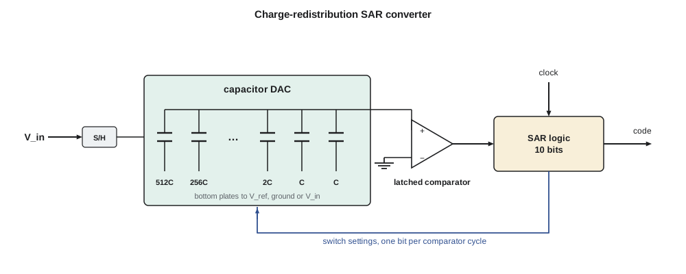
SAR converters dominate the medium-resolution, low-power region of data converters, typically 8 to 16 bits at kilosamples to tens of megasamples per second, because they need only one comparator, a capacitor array and simple logic, nearly all of which draws power only when switching. A 10-bit SAR at 100 kS/s in a 180 nm process can be built to consume tens of microwatts while converting and nothing between conversions.
The charge-redistribution capacitor DAC
In a charge-redistribution SAR the DAC is an array of binary-weighted capacitors: for 10 bits, capacitors of 512, 256, down to 1 unit for the least significant bit, plus a dummy unit so that the total is 1 024 units. During sampling the top plates connect to a common node and the bottom plates to the input, so the array stores a charge proportional to the input. During conversion the top plates float, connected to the comparator, and each bottom plate is switched to the reference or ground according to the trial code. The top-plate voltage then equals the trial DAC voltage minus the input, and the comparator needs only to tell whether it is positive or negative. The array samples, subtracts and generates the DAC voltage at once, with no op-amp.
The array's accuracy depends on the ratios of its capacitors, and it is drawn exactly as lesson 7 prescribed: every capacitor is built from identical unit capacitors, 5 fF MIM or MOM units here, placed in a common-centroid array with dummies around its edge, so that the 512-unit MSB capacitor is truly 512 times the LSB unit. Two limits set the unit size. Thermal noise sampled onto a capacitor has an rms value of √(kT/C), and for a 10-bit converter it must be well below an LSB. Mismatch between units follows Pelgrom's law, with a σ that falls as one over the square root of each unit's area, and it limits linearity.
With a total of 1 024 units of 5 fF, the array is 5.12 pF, its kT/C noise is about 28 µV rms, and one LSB of the 1.2 V range is 1.17 mV. Noise is forty times below an LSB, so the unit size is set by matching rather than noise.
Linearity: DNL and INL
An ideal converter's code transitions are spaced exactly one LSB apart. Differential nonlinearity (DNL) is the deviation of each code's actual width from one LSB; a DNL of −1 means a missing code, a code that no input produces. Integral nonlinearity (INL) is the deviation of each transition from the ideal straight line, which is the running sum of the DNL. The worst errors in a binary-weighted array usually appear at the major transitions, where a large capacitor replaces all the smaller ones. At midscale the 512-unit MSB capacitor turns on while 511 units turn off, and any mismatch between the MSB and the sum of the rest appears as a step in the transfer curve.
Amara simulates the converter with random mismatch: each unit capacitor varies with a σ of 1 %, so a capacitor of k units has a fractional σ of 1 %/√k. The script then sweeps a fine ramp through the converter to measure each code's width, and runs a sine wave through it with and without comparator noise.
import math, random
# 10-bit SAR ADC with a binary-weighted capacitor DAC (illustrative), Vref = 1.2 V
random.seed(11)
NB, VREF = 10, 1.2
cu = 5e-15                        # unit capacitor, F
sigma_u = 0.01                    # 1 % random mismatch of one unit capacitor
caps = []
for k in range(NB):               # MSB has 2^9 units; each unit varies independently
    units = 2 ** k
    caps.append(units * cu * (1 + random.gauss(0, sigma_u / math.sqrt(units))))
caps = caps[::-1]                 # caps[0] is the MSB
c_dummy = cu
c_tot = sum(caps) + c_dummy
print(f"total DAC capacitance {c_tot * 1e12:.2f} pF; kT/C noise {math.sqrt(1.38e-23 * 300 / c_tot) * 1e6:.0f} uV rms")
print(f"1 LSB = {VREF / 2 ** NB * 1e3:.3f} mV")

def convert(vin, comp_offset=0.0, comp_noise=0.0):
    code = 0
    for bit in range(NB):
        trial = code | (1 << (NB - 1 - bit))
        vdac = VREF * sum(c for i, c in enumerate(caps) if trial >> (NB - 1 - i) & 1) / c_tot
        noise = random.gauss(0, comp_noise) if comp_noise else 0.0
        if vin + comp_offset + noise >= vdac:
            code = trial
    return code

# Find each code transition with a fine ramp, then DNL and INL
steps = 2 ** NB * 32
hist = [0] * 2 ** NB
for i in range(steps):
    v = (i + 0.5) * VREF / steps
    hist[convert(v)] += 1
ideal = steps / 2 ** NB
dnl = [h / ideal - 1 for h in hist[1:-1]]
inl, acc = [], 0.0
for d in dnl:
    acc += d; inl.append(acc)
print(f"DNL max {max(dnl):+.2f} LSB, min {min(dnl):+.2f} LSB (worst near code {dnl.index(min(dnl)) + 1})")
print(f"INL max {max(inl):+.2f} LSB, min {min(inl):+.2f} LSB; missing codes: {sum(1 for h in hist if h == 0)}")
# Major transitions, where a large capacitor replaces all the smaller ones, are the usual suspects
for code in (128, 256, 512, 768):
    print(f"  code {code - 1}, just below the {code} transition: DNL {dnl[code - 2]:+.2f} LSB")
# Comparator noise: effect on the effective number of bits for a full-scale-ish sine
def enob(comp_noise, n=2048):
    err2 = 0.0
    for k in range(n):
        v = VREF / 2 + 0.49 * VREF * math.sin(2 * math.pi * 67 * k / n)
        c = convert(v, comp_noise=comp_noise)
        err2 += ((c + 0.5) * VREF / 2 ** NB - v) ** 2
    sig = (0.49 * VREF) ** 2 / 2
    sndr = 10 * math.log10(sig / (err2 / n))
    return sndr, (sndr - 1.76) / 6.02
for cn in (0.0, 0.3e-3, 1.0e-3):
    s, e = enob(cn)
print(f"comparator noise {cn * 1e3:.1f} mV rms: SNDR {s:.1f} dB, ENOB {e:.2f} bits")total DAC capacitance 5.12 pF; kT/C noise 28 uV rms 1 LSB = 1.172 mV DNL max +0.16 LSB, min -0.28 LSB (worst near code 255) INL max +0.28 LSB, min -0.28 LSB; missing codes: 0 code 127, just below the 128 transition: DNL +0.16 LSB code 255, just below the 256 transition: DNL -0.28 LSB code 511, just below the 512 transition: DNL -0.19 LSB code 767, just below the 768 transition: DNL -0.28 LSB comparator noise 0.0 mV rms: SNDR 61.1 dB, ENOB 9.86 bits comparator noise 0.3 mV rms: SNDR 59.1 dB, ENOB 9.52 bits comparator noise 1.0 mV rms: SNDR 52.9 dB, ENOB 8.49 bits
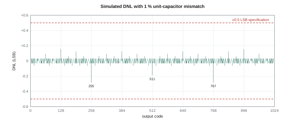
The DNL stays within +0.16 and −0.28 LSB, with the worst values at codes 255 and 767, just below the transitions where the 256-unit capacitor switches. The INL stays within ±0.28 LSB, and there are no missing codes. With 1 % units, mismatch costs almost nothing at 10 bits: the effective number of bits (ENOB) from a sine test is 9.86 without comparator noise, against 9.97 for an ideal converter. The specification of ±0.5 LSB DNL and INL is met with margin. A 12-bit version of the same array would not be so lucky, because its LSB would be four times smaller relative to the same mismatch.
Comparator noise is a separate limit. With 0.3 mV rms of comparator noise, a quarter of an LSB, the ENOB falls to about 9.5 bits; with 1 mV it falls to 8.5. Comparator noise is reduced by larger input devices and more preamplifier current, both of which cost power, or by repeating the last decisions and voting. Priya's budget allows 0.3 mV rms, which gives an ENOB above 9.5 bits, more than the volume control needs.
Worked problem
Choosing the unit capacitor
A designer wants a 12-bit SAR with a 1.2 V range. What total capacitance makes the kT/C noise one tenth of an LSB at 300 K? If unit capacitors have σ = 1 %/√(C/5 fF), is that total also enough for matching?
Show solution
- \[\text{1 LSB} = \frac{1.2}{4096} = 293\ \mu\text{V} \Rightarrow v_n \le 29.3\ \mu\text{V}\]
- \[C_{\text{tot}} \ge \frac{kT}{v_n^2} = \frac{4.14\times10^{-21}}{(29.3\times10^{-6})^2} \approx 4.8\ \text{pF}\]
- That gives a unit of 4.8 pF/4096 ≈ 1.2 fF, whose σ would be about 1 %/√0.24 ≈ 2 %. For 12 bits the MSB mismatch must be well under half an LSB, which needs unit σ near 0.5 %, so matching, not noise, sets a unit of about 20 fF and a total near 80 pF unless the array is calibrated.
Answer: Noise alone needs about 5 pF, but matching needs far more without calibration. That is why high-resolution SAR converters use calibration or split arrays.
Practical refinements
Several refinements are standard in modern SAR converters and worth knowing. A split capacitor array, with a small bridging capacitor between an upper and lower section, reduces the total capacitance and the switching energy by orders of magnitude, at some cost in linearity. Energy-efficient switching schemes, of which there are many, avoid the wasted charge of switching the MSB capacitor on and then off when a bit is rejected. Redundancy, giving the DAC slightly more than binary weighting so that a wrong early decision can be corrected later, relaxes the settling and noise requirements on the early bits. Asynchronous SAR logic, which starts each comparison as soon as the previous one has resolved, removes the need for a fast internal clock. And foreground calibration, measuring each capacitor's error at test and correcting it in logic, lets a 180 nm SAR reach 14 bits or more.
The CX-1 converter uses none of these except a simple asynchronous controller: its 10 bits at 100 kS/s are well within the reach of a plain binary array. Its sampling switch is a bootstrapped transmission gate, whose gate voltage tracks the input so that its on-resistance stays constant and the sampled signal is not distorted, and its reference comes from the buffered bandgap of lesson 8, decoupled with a large on-chip capacitor so that the charge drawn by the array during each bit trial does not disturb it.
Other converter types
For completeness, the other common architectures occupy other corners of the speed-resolution plane. Flash converters use 2^N − 1 comparators to convert in one step and are the fastest, but practical only up to about 6 to 8 bits. Pipelined converters chain low-resolution stages with residue amplifiers and reach 10 to 14 bits at hundreds of megasamples per second, at much higher power. Sigma-delta converters oversample with a coarse quantizer inside a feedback loop and shape the quantization noise out of the signal band, reaching 16 to 24 bits at audio and lower bandwidths; they are the usual choice for high-quality audio. Had CX-1 needed to record speech with high fidelity rather than measure its level, Priya would have designed a sigma-delta. The digital-to-analog side of the APS-2, the voice messages, stays in the product's microcontroller and its class-AB speaker driver of ELE-340.
Common mistakes
MistakeUsing a compensated op-amp as a converter's comparator.
InsteadIts compensation makes it slow; use a latched regenerative comparator with a preamplifier.
MistakeSizing the capacitor array from kT/C noise alone.
InsteadMismatch usually sets the unit size at 10 bits and above unless the array is calibrated.
MistakeTreating comparator offset and noise alike.
InsteadOffset shifts all codes and can be calibrated; noise reduces the ENOB and cannot.
MistakeDrawing the MSB capacitor as one large plate.
InsteadBuild every capacitor from identical units in a common-centroid array so that the ratios hold.
Summary and key terms
- Continuous comparators use hysteresis to reject noise; converter comparators use regenerative latches whose decision time grows with ln(1/ΔV).
- A preamplifier ahead of the latch speeds decisions, isolates kickback and reduces offset.
- A SAR converter performs a binary search with one comparator and a DAC, one bit per cycle.
- In a charge-redistribution SAR the binary-weighted capacitor array samples, subtracts and generates the DAC voltage.
- kT/C noise and unit-capacitor mismatch set the array size; DNL and INL errors peak at major transitions.
- The CX-1 10-bit SAR with 1 % units achieves DNL and INL within ±0.3 LSB and about 9.5 ENOB with its comparator noise.
- Hysteresis
- Different switching thresholds for rising and falling inputs, used to reject noise.
- Regenerative comparator
- A comparator that amplifies an input imbalance by positive feedback in a latch.
- StrongARM latch
- A clocked comparator combining an input pair and a cross-coupled latch with no static current.
- SAR converter
- An analog-to-digital converter that finds the code by binary search, one bit per cycle.
- Capacitor DAC
- A binary-weighted capacitor array that generates trial voltages by charge redistribution.
- DNL
- Differential nonlinearity, the deviation of each code width from one LSB.
- INL
- Integral nonlinearity, the deviation of each transition from the ideal straight line.
- ENOB
- Effective number of bits, (SNDR − 1.76)/6.02.
Practice problems
Work each problem on paper first, then reveal the answer to check.
Find one LSB of a 10-bit converter with a 1.2 V range.
Show answer
1.17 mV.
What is the kT/C noise of a 2 pF capacitor at 300 K?
Show answer
√(4.14×10⁻²¹/2×10⁻¹²) ≈ 45 µV.
A converter's SNDR is 58 dB. Find its ENOB.
Show answer
(58 − 1.76)/6.02 ≈ 9.3 bits.
How many comparator cycles does a 12-bit SAR conversion need?
Show answer
12, plus sampling.
A latch has τ = 50 ps and must resolve 1 mV to 0.9 V. Estimate its decision time.
Show answer
50 ps × ln(900) ≈ 340 ps.
Where in a binary-weighted SAR are DNL errors usually largest?
Show answer
At the major transitions, such as midscale, where a large capacitor replaces all the smaller ones.
Lesson quiz · 5 questions
Score 60% or more to complete this lesson.
Create a free account to save your progress, take quizzes and earn a certificate.