
DCT-330 · Lesson 11 of 12 · 19 min
Site documentation and the single-line diagram
A live facility is understood through its documents. Nobody can see a cable buried in a duct bank or a breaker's position inside a closed switchboard; the drawings, schedules and records say where everything is and how it connects. This lesson covers the documents a data centre technician uses most, how to read a single-line diagram, and how documents are kept true to the building. It is about reading and maintaining documents, not designing systems: the engineering of the power system belongs to the engineers, and to the DCE school, especially DCE-310 and DCE-340.
The documents of a facility
Stonebridge's operations documents fall into a few families:
- Drawings: architectural floor plans, electrical single-line diagrams and riser diagrams, mechanical flow diagrams for the chilled water and coolant systems, fire protection and security layouts, and cable pathway drawings. Each has a number, a revision and a title block.
- Schedules and lists: panel schedules listing every breaker and what it feeds, equipment lists with ratings, valve lists, point lists for the BMS and EPMS, and the alarm database (lesson 4).
- As-built records: drawings and schedules updated after construction or changes to show what was actually installed, which often differs from the design.
- Equipment manuals and data sheets: the makers' instructions for operation and maintenance.
- Procedures: MOPs, SOPs and EOPs (lesson 10).
- The DCIM model (lesson 5), which holds much of the same information in database form and links it to live data.
These overlap, and the overlaps are where errors hide: a breaker that the panel schedule says feeds A-31-03, the drawing says feeds A-31-04 and DCIM says feeds both. One of the desk's quiet jobs is to notice such disagreements and get them resolved.
The single-line diagram
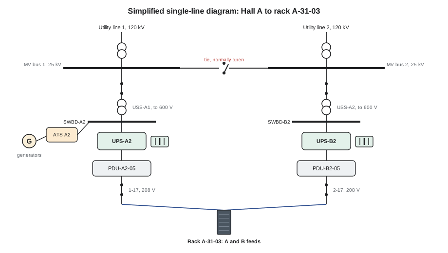
The single-line diagram (SLD), also called a one-line diagram, shows a power system's connections using one line for each three-phase circuit, with symbols for the equipment. It is the most important drawing in a data centre, because it is how everyone, from the electrician opening a breaker to the shift lead assessing an outage, understands which path power takes and what depends on what. The EPMS one-line overview on the desk wall is a live version of it.
Reading an SLD starts at the top, where power enters, and follows the lines downward:
- Sources: utility incoming lines, generators, and sometimes solar or battery systems, at the top or the edges.
- Transformers: two overlapping circles, with the voltages on each side.
- Buses: thick horizontal lines in switchgear and switchboards, to which several circuits connect.
- Breakers and switches: small boxes or symbols on each line, shown open or closed in their normal state, with their names and ratings.
- Transfer switches: symbols connecting two sources to one load.
- UPS systems, PDUs and RPPs: boxes with their names and ratings.
- Loads: at the bottom: floor PDUs, mechanical panels, and ultimately racks.
Each piece of equipment carries the same name on the SLD as on its label and in DCIM, which is why consistent naming (DCT-130, DCT-220) matters so much. A normally open breaker, such as SUB-1's tie breaker between the two medium-voltage buses (DCT-220 lesson 2), is drawn open; anyone reading the drawing can see at a glance which paths are normally live and which are standby.
Reading the SLD for a task
Technicians use the SLD for three common questions. Upstream: what feeds this equipment, and what would have to fail or be switched for it to lose power? Downstream: what depends on this equipment, and what would lose power if it were opened? Redundancy: is this load fed by two independent paths all the way up, or do the paths join somewhere? The DCIM connection trace (lesson 5) answers the same questions from its database, and comparing the two is a good check on both.
The third question matters most in planning work. Two paths that look separate at the rack may meet higher up: two PDUs fed from the same UPS, or two UPS systems fed from the same switchboard. Such a shared point is a single point of failure, and an SLD is the clearest way to find one. Stonebridge's design keeps the A and B sides separate from the rack up to the unit substations, and the SLD shows it.
# Trace upstream from a rack feed through a simplified SLD and check that A and B are independent
feeds = {  # item: what feeds it
    "A-31-03 A": "PDU-A2-05 br 1-17", "A-31-03 B": "PDU-B2-05 br 2-17",
    "PDU-A2-05 br 1-17": "PDU-A2-05", "PDU-B2-05 br 2-17": "PDU-B2-05",
    "PDU-A2-05": "UPS-A2", "PDU-B2-05": "UPS-B2",
    "UPS-A2": "SWBD-A2", "UPS-B2": "SWBD-B2",
    "SWBD-A2": "USS-A1", "SWBD-B2": "USS-A2",
    "USS-A1": "MV bus 1", "USS-A2": "MV bus 2", "MV bus 1": "SUB-1", "MV bus 2": "SUB-1",
}
def upstream(item):
    path = [item]
    while path[-1] in feeds:
        path.append(feeds[path[-1]])
    return path
a, b = upstream("A-31-03 A"), upstream("A-31-03 B")
print("A path:", " <- ".join(a))
print("B path:", " <- ".join(b))
shared = [x for x in a if x in b]
print("First shared item:", shared[0] if shared else "none")A path: A-31-03 A <- PDU-A2-05 br 1-17 <- PDU-A2-05 <- UPS-A2 <- SWBD-A2 <- USS-A1 <- MV bus 1 <- SUB-1 B path: A-31-03 B <- PDU-B2-05 br 2-17 <- PDU-B2-05 <- UPS-B2 <- SWBD-B2 <- USS-A2 <- MV bus 2 <- SUB-1 First shared item: SUB-1
The two paths are separate all the way to the substation, SUB-1, which has two utility lines and two transformers of its own (DCT-220 lesson 2). Only at the campus level do they meet, which is why the campus also has generators.
Panel schedules and labels
A panel schedule lists every breaker in a panelboard, PDU or RPP: its number, rating, number of poles, and what it feeds. It is usually posted inside the panel door and kept in the document system and DCIM. When Jamal traced breaker 2-17 for the electrician in lesson 5, the panel schedule, DCIM and the label on the rack receptacle all had to agree. When they do not, the floor is checked and the records corrected by ticket.
Labels on equipment are part of the documentation. The rule from DCT-130 applies across the site: every breaker, receptacle, cable, valve, sensor and panel has a label that matches the drawings and DCIM, printed, durable and legible. A handwritten label is a temporary fix that must be replaced. A missing label is a P4 ticket; a label that is wrong is more serious, because people trust it.
Mechanical and liquid cooling drawings
Mechanical systems have their own diagrams: chilled water and coolant flow diagrams show pumps, valves, heat exchangers, sensors and pipe sizes, with flow directions and normal valve positions; they are the cooling equivalent of the SLD. DCT-230 used them to trace Hall D's loops from the dry coolers through the CDUs to the racks. Valve lists give every valve's tag, location, normal position and purpose. As with electrical drawings, the tags on the drawing, the label on the valve and the point names in the BMS must agree. The valve left partly open in the DCT-230 capstone was found quickly because its tag led straight to its place on the flow diagram.
Keeping documents true
Documents drift from reality whenever the facility changes and the records do not. The main defences are the ones built into this course: every change ends with record updates as part of its close-out (lesson 9); every MOP is walked down against the drawings (lesson 10); DCIM is audited monthly (lesson 5); and anyone who finds a mismatch raises a ticket. Stonebridge also has a red-line process: during work, the person in charge marks any difference between the drawing and the as-installed condition in red on a copy, and that marked copy goes to the document owner, who updates the controlled drawing and issues a new revision.
Revisions are tracked in each drawing's title block: the revision letter or number, date, description and who approved it. A technician using a drawing checks that it is the current revision from the document system, not a copy from a folder. Out-of-date drawings in the field are a known cause of mistakes; Stonebridge marks printed drawings with the date printed and 'check revision before use'.
# Reconcile the as-built panel schedule with DCIM for PDU-B2-05 (extract)
schedule = {  # breaker: (rating A, feeds)   from the as-built panel schedule
    "2-15": (30, "A-31-01 B"), "2-16": (30, "A-31-02 B"), "2-17": (30, "A-31-03 B"),
    "2-18": (30, "A-31-04 B"), "2-19": (60, "A-31-05 B"), "2-20": (30, "spare"),
}
dcim = {
    "2-15": (30, "A-31-01 B"), "2-16": (30, "A-31-02 B"), "2-17": (30, "A-31-03 B"),
    "2-18": (30, "A-31-05 B"), "2-19": (60, "A-31-05 B"), "2-21": (30, "A-31-06 B"),
}
for br in sorted(set(schedule) | set(dcim)):
    s, d = schedule.get(br), dcim.get(br)
    if s == d: continue
    if s is None: print(f"breaker {br}: in DCIM ({d[1]}) but not on the schedule")
    elif d is None: print(f"breaker {br}: on the schedule ({s[1]}) but not in DCIM")
else: print(f"breaker {br}: schedule {s[0]} A to {s[1]}, DCIM {d[0]} A to {d[1]}")breaker 2-18: schedule 30 A to A-31-04 B, DCIM 30 A to A-31-05 B breaker 2-20: on the schedule (spare) but not in DCIM breaker 2-21: in DCIM (A-31-06 B) but not on the schedule
Three mismatches, three tickets. Breaker 2-18 feeds A-31-04 on the schedule but A-31-05 in DCIM; since 2-19 also feeds A-31-05 in both, DCIM is probably wrong, but the floor must be checked. Breaker 2-20 is a spare on the schedule but missing from DCIM, which means DCIM's capacity view undercounts free breakers. Breaker 2-21 is in DCIM but not on the schedule: either the schedule is out of date or the DCIM record is for a breaker that does not exist. Roz checked all three on her next round.
Documents during an incident
When something fails, the documents are what the team works from. The shift lead opens the SLD or flow diagram, marks the failed equipment, and works out the current state: which paths are live, what is at N, what depends on the failed part. The relevant EOP gives the steps. A team that has to find the right drawing during an incident, or discovers that it is out of date, loses minutes it may not have. That is why Stonebridge keeps the current SLDs and main flow diagrams printed and laminated in the operations room and at each electrical room door, as well as in the document system, and checks their revisions every quarter.
Worked problem
A drawing that no longer matches
Preparing a MOP to replace UPS-B2's maintenance bypass breaker, the engineer uses the SLD revision F from the document system. On the walk-down, Jamal finds that the UPS output switchboard has an extra feeder breaker, labelled SWBD-B2-OUT-07, that is not on revision F. What happens?
Show solution
- Jamal stops and reports it. He photographs the breaker, its label and its position in the board.
- Roz checks DCIM: OUT-07 feeds a new floor PDU, PDU-B2-09, installed eight months earlier under a change whose close-out did not include the SLD update.
- The engineer confirms OUT-07 is fed from the UPS output bus, so the MOP must account for it: during bypass work, PDU-B2-09's loads will be affected in the same way as the others.
- The MOP is revised and re-reviewed. A ticket goes to the document owner, who issues SLD revision G from the red-lined copy.
- A problem ticket asks why the earlier change closed without its drawing update; the change close-out checklist gains a line for SLD revisions.
Answer: An eight-month-old records gap was caught before it could cause an error during maintenance on a live UPS.
Common mistakes
MistakeUsing a drawing from a folder without checking its revision.
InsteadCheck the current revision in the document system before use.
MistakeAssuming A and B paths are independent because they are separate at the rack.
InsteadTrace both upstream on the SLD to find any shared point.
MistakeWriting a new label by hand and leaving it.
InsteadHandwritten labels are temporary; ticket a printed one.
MistakeCorrecting a panel schedule by hand without telling the owner.
InsteadRed-line it and send it to the document owner for a new revision.
MistakeClosing a change before the drawings are updated.
InsteadRecord updates, including the SLD, are part of the close-out.
Summary and key terms
- Facilities are understood through drawings, schedules, as-built records, manuals, procedures and DCIM, which must agree.
- The single-line diagram shows how power flows from sources through transformers, buses, breakers, UPS and PDUs to the loads, with normal breaker states.
- Tracing upstream and downstream on the SLD answers what feeds what, what depends on what, and where paths share a single point of failure.
- Panel schedules, valve lists and labels must match the drawings and DCIM; mismatches are ticketed and checked on the floor.
- Red-lines, revisions and document control keep drawings true; every change closes with record updates.
- Current drawings must be quickly available during incidents.
- Single-line diagram
- A drawing showing a power system's connections with one line per circuit and symbols for equipment.
- Panel schedule
- A list of every breaker in a panel, its rating and what it feeds.
- As-built
- A record updated to show what was actually installed.
- Red-line
- A marked-up copy of a drawing showing differences found in the field.
- Revision
- A numbered or lettered version of a controlled document.
- Single point of failure
- A component whose failure alone would interrupt the load.
Practice problems
Work each problem on paper first, then reveal the answer to check.
How is a normally open tie breaker shown on an SLD?
Show answer
Drawn open, with its name, so normal and standby paths are clear.
Two rack feeds come from different PDUs, but both PDUs are fed from the same UPS. What is that?
Show answer
A single point of failure at the UPS; the feeds are not independent.
A panel schedule shows a breaker as spare but DCIM has no record of it. Why does that matter?
Show answer
DCIM undercounts free capacity; the records must be reconciled.
What is a red-line copy for?
Show answer
Marking field differences so the document owner can issue a corrected revision.
Lesson quiz · 5 questions
Score 60% or more to complete this lesson.
Create a free account to save your progress, take quizzes and earn a certificate.