
DCT-210 · Lesson 7 of 12 · 19 min
Polarity methods and breakouts
Every optical link has to get each transmitter's light to the receiver at the other end. With a single duplex cord between two devices, that is easy: the cord crosses the two fibres, so transmit at one end meets receive at the other. Through a structured plant with trunks, cassettes, adapters and cords from different makers, it is not easy at all, and a link that is wired with its transmitters facing each other simply never comes up. Keeping track of which way each fibre goes is called polarity, and Nadia says it causes more confused technicians than any other topic in the course. LVT-210 introduced it for duplex links; this lesson adds the multi-fibre parallel links that dominate the newer halls.
The basic problem
Picture a duplex link. Device 1 transmits on fibre position A and receives on B. Device 2 also transmits on A and receives on B. For the link to work, position A at device 1 must arrive at position B at device 2, and the other fibre the other way. Each component in the path either keeps the order of the fibres, straight through, or swaps it. The rule is simple: the whole channel must swap an odd number of times. One swap works; two swaps put transmit against transmit; three swaps work again.
The same idea extends to parallel links. A 400G-DR4 transceiver transmits on MPO positions 1 to 4 and receives on 9 to 12. For the link to work, position 1 at one end must arrive at position 12 at the other, 2 at 11, 3 at 10 and 4 at 9: the whole row must be reversed an odd number of times.
Trunk types
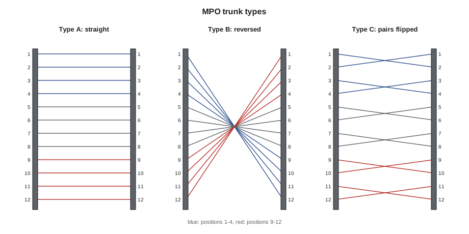
The TIA-568.3 standard, whose current edition is TIA-568.3-E, defines three types of MPO trunk by what happens to the fibre order between the two ends:
- Type A, key-up to key-down: position 1 at one end arrives at position 1 at the other. Viewed in the usual way, the order is kept straight.
- Type B, key-up to key-up: position 1 arrives at position 12, or 16 on an MPO-16. The whole row is reversed.
- Type C, key-up to key-down with each pair crossed: position 1 arrives at 2, 2 at 1, 3 at 4, and so on. Each pair is flipped but the row keeps its order.
Patch cords come in two kinds too. Duplex cords are A-to-B, a normal crossover cord, or A-to-A, a straight cord used in particular designs. MPO cords are made in the same Types A, B and C as trunks.
Polarity methods
A polarity method is a recipe of trunk type, adapter type and cord types that always produces a working channel. TIA-568.3 describes:
- Method A: Type A trunk, with an A-to-B cord at one end and an A-to-A cord at the other for duplex links.
- Method B: Type B trunk, with A-to-B cords at both ends.
- Method C: Type C trunk, with A-to-B cords at both ends.
For parallel links there are corresponding methods using Type A or Type B MPO trunks and the matching MPO cords. Each method works when every component in it is the right type; mixing components from two methods is what breaks links. The point for a technician is not to memorize the recipes but to know which method each hall uses, to install only components of that method, and to recognize a polarity fault when a link will not come up.
| Hall | Links | Method | What a technician installs |
|---|---|---|---|
| Hall A | Duplex multimode and single-mode through cassettes | Method B | Type B trunks, Method B cassettes, A-to-B duplex cords at both ends |
| Halls B and C | 400G-DR4 parallel, some 4x100G breakouts | Method B (parallel) | Type B base-8 trunks, Type B MPO cords, approved harnesses |
| Hall D backend | 800G-DR8 parallel on MPO-16 | Method B (parallel) | Type B base-16 trunks, Type B MPO-16 APC cords |
| Hall D frontend | 2x400G-FR4 duplex | Method B | Cassettes and A-to-B duplex LC APC cords |
Nadia chose Method B for the whole campus years ago because it needs only one type of duplex cord, A-to-B, everywhere. Customers in their own cages may use other methods; their port maps say which.
Checking polarity with a map
A technician can check a channel on paper before installing it by following one fibre position through each component. Nadia has Jamal write the components of a channel as a list and let the computer follow the lanes.
# Follow each transmit lane of a parallel link through the channel and check it lands on a receive position
def type_a(n, size): return n
def type_b(n, size): return size + 1 - n
def type_c(n, size): return n + 1 if n % 2 else n - 1

def check(name, parts, size, tx, rx):
    landed = []
    for lane in tx:
        pos = lane
        for part in parts:
            pos = part(pos, size)
        landed.append(pos)
    ok = sorted(landed) == sorted(rx)
    print(f"{name:40} -> lands on {landed}  {'OK' if ok else 'FAULT: transmitters face transmitters'}")

dr4_tx, dr4_rx = [1, 2, 3, 4], [9, 10, 11, 12]
dr8_tx, dr8_rx = list(range(1, 9)), list(range(9, 17))
check("DR4: B cord, B trunk, B cord", [type_b, type_b, type_b], 12, dr4_tx, dr4_rx)
check("DR4: A cord, B trunk, A cord", [type_a, type_b, type_a], 12, dr4_tx, dr4_rx)
check("DR4: B cord, B trunk, A cord (mixed)", [type_b, type_b, type_a], 12, dr4_tx, dr4_rx)
check("DR8: B cord, B trunk, B cord (Hall D)", [type_b, type_b, type_b], 16, dr8_tx, dr8_rx)
check("DR8: C cord, B trunk, B cord (wrong cord)", [type_c, type_b, type_b], 16, dr8_tx, dr8_rx)DR4: B cord, B trunk, B cord -> lands on [12, 11, 10, 9] OK DR4: A cord, B trunk, A cord -> lands on [12, 11, 10, 9] OK DR4: B cord, B trunk, A cord (mixed) -> lands on [1, 2, 3, 4] FAULT: transmitters face transmitters DR8: B cord, B trunk, B cord (Hall D) -> lands on [16, 15, 14, 13, 12, 11, 10, 9] OK DR8: C cord, B trunk, B cord (wrong cord) -> lands on [2, 1, 4, 3, 6, 5, 8, 7] FAULT: transmitters face transmitters
Three reversals or one reversal both work; two reversals, or a pair-flipped cord in a parallel channel, do not. In the real plant the adapters' key orientation is part of each component's type, which is why the method is specified as a whole and the components are bought to match.
Breakouts
A breakout runs one high-speed port as several lower-speed links. A 400G-DR4 port is four lanes of 100 Gb/s, and it can be used as four separate 100G-DR links, each on one fibre pair, to four different servers. The cable that does this is a harness, or fan-out cord, with an MPO on one end and four duplex LC connectors on the other, or a cassette that does the same inside the panel. Each duplex leg takes one transmit position and the matching receive position: positions 1 and 12, 2 and 11, 3 and 10, 4 and 9 in the usual design, labelled as legs 1 to 4.
Breakouts are common in Halls B and C, where the cloud provider connects 100G servers to 400G switch ports, and in Hall D's management and storage networks. They have three traps. The legs must be connected in the order the port map says, because the switch configures each lane as a separate port. The duplex legs still need the right polarity, which the harness design takes care of if the right harness is used. And the breakout has to be allowed by the switch and the transceiver: not every 400G optic can be split.
# Map the legs of a 400G-DR4 breakout harness to the switch's lane ports and the servers
switch_port = "Ethernet1/17"
servers = ["srv-b12-21", "srv-b12-22", "srv-b12-23", "srv-b12-24"]
for leg in range(1, 5):
    tx, rx = leg, 13 - leg
    lane_port = f"{switch_port}/{leg}"
print(f"leg {leg}: MPO positions {tx:2} and {rx:2} -> {lane_port:15} -> {servers[leg - 1]}")leg 1: MPO positions 1 and 12 -> Ethernet1/17/1 -> srv-b12-21 leg 2: MPO positions 2 and 11 -> Ethernet1/17/2 -> srv-b12-22 leg 3: MPO positions 3 and 10 -> Ethernet1/17/3 -> srv-b12-23 leg 4: MPO positions 4 and 9 -> Ethernet1/17/4 -> srv-b12-24
Finding a polarity fault
A polarity fault looks like a dead link: no light received at either end, though both transceivers are transmitting. The first checks are always the same as for any optical fault, inspect and clean, but if the end faces are clean and the link is still dead, polarity is the next suspect. A visual fault locator or the transceiver's own diagnostics show where the light goes: shining the locator into position 1 at one end and looking with a power meter or the far transceiver's receive power shows which position it arrives at. A light source and power meter set for MPO, or an MPO polarity tester, can check all twelve or sixteen positions at once and show the map.
The fix is never a field modification of a trunk. A technician replaces the wrong component, usually a cord or cassette of the wrong type, with the right one, and records the change. Flipping fibres inside a connector or using an adapter of the opposite key type to correct a fault leaves a plant that no one can understand later.
Worked problem
A new Hall B link that would not come up
The cloud provider's engineer reports that a new 400G link from leaf B-12-09 to network cabinet B-NET-04 shows no receive light at either end. The ticket says Jamal installed Type B MPO cords at both ends on a Type B trunk.
Show solution
- Jamal inspects and cleans all four MPO end faces in the channel. The link stays dark.
- He connects Stonebridge's MPO polarity tester to the cord at B-12-09 and the matching receiver at B-NET-04. It shows position 1 arriving at position 1: the channel has an even number of reversals.
- He checks each component's label. The cord at B-NET-04 is a Type A cord, picked from a bin where someone had returned it to the wrong shelf.
- He replaces it with a Type B cord, inspects the new end faces and reconnects. The tester shows 1 to 12, and the link comes up. He reports the mixed-up bin to stores.
Answer: The channel was a mixture of two methods. Replacing the one wrong component fixed it; no fibres were moved.
Polarity in a customer's cage
Customers who cable their own cages may use a different polarity method, or components from a maker whose types are named differently. Some makers label their cords with their own codes rather than A, B and C, and some cassettes are made in mirror-image pairs that must be installed at the right ends. Before Jamal works inside a cage, he reads the customer's cabling standard or asks for it, and he never mixes Stonebridge stock with a customer's components in one channel. Where a Stonebridge panel meets a customer's panel, at the demarcation point in the cage, the port map shows which side's method each segment follows and which cord type joins them, so that the channel as a whole still has the odd number of reversals it needs.
The same caution applies when equipment is upgraded. A Hall A cage cabled for duplex links through cassettes cannot simply carry parallel 400G links: the cassettes split the trunk legs into pairs, and a parallel transceiver needs the whole leg. Upgrading such a cage means replacing the cassettes with pass-through panels of the right method, or adding new trunks, which is a design change handled by Nadia, not a cord swap a technician can make on a ticket.
Nadia's simplest advice on polarity is to treat every channel as a list of components and to know the type of each one. If every component is of the type the hall's method calls for, the channel will work; if a link is dead after cleaning, the list shows which component to suspect first.
Common mistakes
MistakeMixing cords and trunks from different polarity methods.
InsteadInstall only components of the hall's method; check the type on each label.
MistakeCorrecting a polarity fault by flipping fibres in a connector.
InsteadReplace the wrong component with the right type.
MistakePlugging breakout legs into servers in any order.
InsteadFollow the port map: each leg is a separate switch port.
MistakeAssuming every 400G optic can be broken out.
InsteadCheck that the switch and transceiver support it.
MistakeJumping to polarity before cleaning.
InsteadInspect and clean first; then check polarity.
Summary and key terms
- A working channel swaps or reverses the fibre order an odd number of times.
- Type A trunks keep the order, Type B reverse it, Type C flip each pair.
- A polarity method is a recipe of trunk, adapter and cord types; Stonebridge uses Method B throughout.
- Parallel links need transmit positions to land on receive positions: 1–4 onto 12–9 for DR4.
- Breakout harnesses split a parallel port into duplex legs that must follow the port map.
- Fix polarity faults by replacing the wrong component, never by rebuilding connectors.
- Polarity
- The arrangement that gets each transmitter's light to the right receiver.
- Type A, B and C
- MPO trunk types that keep, reverse or pair-flip the fibre order.
- Polarity method
- A defined combination of trunk, adapter and cord types that produces a working channel.
- A-to-B cord
- A duplex cord that crosses its two fibres.
- Breakout
- Running one parallel port as several lower-speed links.
- Harness
- A cord with an MPO on one end and several duplex connectors on the other.
Practice problems
Work each problem on paper first, then reveal the answer to check.
A channel has a Type B trunk and Type B MPO cords at both ends. Will a DR4 link work?
Show answer
Yes: three reversals give one overall reversal.
Which MPO positions does breakout leg 3 of a DR4 harness use?
Show answer
Positions 3 and 10.
What tool shows the full position map of an MPO channel?
Show answer
An MPO polarity tester, or a light source and power meter for MPO.
Why does Stonebridge use one polarity method everywhere?
Show answer
It needs only one kind of duplex cord and keeps stock and training simple.
Lesson quiz · 5 questions
Score 60% or more to complete this lesson.
Create a free account to save your progress, take quizzes and earn a certificate.