
DCT-210 · Lesson 11 of 12 · 20 min
Testing and documenting data centre links
A link that works on the day it is installed but cannot be found in the records a year later is, Nadia says, half a link. This lesson covers how Stonebridge proves that its cabling meets its loss budgets, and how every panel, port, trunk and cord ends up in records that the next technician can trust. LVT-130 taught copper certification and LVT-210 taught optical loss testing with a light source and power meter and with an OTDR. Here Jamal applies them to multi-fibre links, to loss budgets that are far tighter than in a building, and to a records system that has to keep up with hundreds of changes a week.
Loss budgets for high-speed links
Every Ethernet optical interface has a maximum channel insertion loss: the most light the cabling between the two transceivers may lose, including fibre and connections, for the link to work reliably. The IEEE standards define it for each interface, and the transceiver makers' data sheets repeat it. For the short-reach multimode interfaces, the budget is small, and it shrinks as the speed and the number of connections rise. Typical figures for Stonebridge's planning are:
| Interface | Fibre | Reach used in planning | Channel loss budget (typical) |
|---|---|---|---|
| 10GBASE-SR | OM4 | 300 m (985 ft) | About 2.9 dB |
| 100GBASE-SR4 and 400GBASE-SR4 | OM4 | 100 m (330 ft) | About 1.9 dB |
| 400GBASE-DR4 | OS2 | 500 m (1,640 ft) | About 3.0 dB |
| 800GBASE-DR8 | OS2 | 500 m (1,640 ft) | About 3.0 dB |
| 400GBASE-FR4 | OS2 | 2 km (1.2 mi) | About 4.0 dB |
Within those budgets, the designer allows for the fibre, which is a small part of a short link, and for the mated connector pairs, which are most of it. A multimode link with a budget of 1.9 dB can afford only two or three mated pairs of ordinary connectors, which is one reason the newer halls use low-loss connectors and pass-through panels. Single-mode parallel links have more room but are more sensitive to reflections, which is why their connectors are angle-polished.
# Check measured loss against the budget for links in three halls (planning values)
links = [
    ("A-31-03 PP1-07 to A-HDA-31 PP4-07", "10GBASE-SR", 2.9, 0.62),
    ("B-12-09 PP1-03 to B-NET-04 PP7-03", "400GBASE-DR4", 3.0, 0.88),
    ("B-14-02 PP1-05 to B-NET-04 PP7-21", "400GBASE-SR4", 1.9, 1.74),
    ("D-3-07 PP2-41 to D-4-02 PP3-41", "800GBASE-DR8", 3.0, 0.71),
    ("D-3-07 PP2-42 to D-4-02 PP3-42", "800GBASE-DR8", 3.0, 3.24),
]
for name, app, budget, measured in links:
    margin = budget - measured
    flag = "PASS" if margin >= 0.3 else ("MARGINAL" if margin >= 0 else "FAIL")
print(f"{name:36} {app:13} {measured:4.2f} of {budget:.1f} dB margin {margin:+.2f} {flag}")A-31-03 PP1-07 to A-HDA-31 PP4-07 10GBASE-SR 0.62 of 2.9 dB margin +2.28 PASS B-12-09 PP1-03 to B-NET-04 PP7-03 400GBASE-DR4 0.88 of 3.0 dB margin +2.12 PASS B-14-02 PP1-05 to B-NET-04 PP7-21 400GBASE-SR4 1.74 of 1.9 dB margin +0.16 MARGINAL D-3-07 PP2-41 to D-4-02 PP3-41 800GBASE-DR8 0.71 of 3.0 dB margin +2.29 PASS D-3-07 PP2-42 to D-4-02 PP3-42 800GBASE-DR8 3.24 of 3.0 dB margin -0.24 FAIL
Stonebridge wants at least 0.3 dB of margin on every new link, so that ageing, a later cleaning or one extra patch does not push it over the edge. The third link passes the standard but is marginal by Stonebridge's rule, and the last one fails; both are inspected and cleaned before anything else, because dirty connections are the usual cause.
Testing multi-fibre links
Trunks are tested twice: at the factory, which supplies a report of the loss of every fibre, and after installation, when the installed permanent link from panel to panel is tested. In the field, Stonebridge uses Tier 1 testing, with a light source and power meter, as its acceptance test, and an OTDR only for faults and for long backbone links, as LVT-210 described.
For MPO links, an MPO light source and power meter test all twelve or sixteen fibres of a leg at once and show the loss of each fibre and the position map, which also checks the polarity from Lesson 7. The reference is set with test reference cords of the same connector type, using the one-cord method where the tester allows it, so that the result includes both end connections of the permanent link. Reference cords are inspected and cleaned before every reference and replaced when they are worn, because a dirty reference cord makes every link look better or worse than it is.
- Test each installed permanent link from panel to panel, not including the equipment cords.
- Test at the wavelengths the links will use: 850 nm, and 1300 nm if required, for multimode; 1310 nm, and 1550 nm where the design asks, for single-mode.
- Compare each fibre with the link's limit, worked out from the design's connector and fibre allowances, and with the factory report.
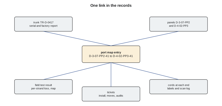
- Save every result with the trunk serial number and the panel and port labels.
Labels in the data centre
Labelling follows ANSI/TIA-606, which LVT-120 covered, with identifiers built from the space and cabinet names of Lesson 2. At Stonebridge every label is printed, never handwritten, and carries the identifier of the thing it is on and, for cables, of both ends:
- Panels: YUL2-D-4-02-PP3, the third panel in network cabinet D-4-02.
- Ports: printed on the panel, PP3-41 for port 41.
- Trunks: the trunk identifier and the panels at each end, on both ends and in the tray at every change of direction, for example TR-D-0417 D-3-07-PP2 to D-4-02-PP3.
- Cords: both end identifiers on a flag or sleeve label at each end, or the cross-connect number for meet-me room cords.
- Customer cords inside cages: to the customer's scheme, but anything that touches Stonebridge's panel also carries the Stonebridge port identifier.
# Generate the end labels for a trunk and its legs
site, hall = "YUL2", "D"
trunk = "TR-D-0417"
a_end, z_end = ("3-07", "PP2"), ("4-02", "PP3")
legs, first_port = 9, 37
print(f"Trunk label: {trunk}  {site}-{hall}-{a_end[0]}-{a_end[1]} <-> {site}-{hall}-{z_end[0]}-{z_end[1]}")
for leg in range(1, legs + 1):
    port = first_port + leg - 1
print(f" leg {leg}: {a_end[1]}-{port:02d} <-> {z_end[1]}-{port:02d}")Trunk label: TR-D-0417 YUL2-D-3-07-PP2 <-> YUL2-D-4-02-PP3 leg 1: PP2-37 <-> PP3-37 leg 2: PP2-38 <-> PP3-38 leg 3: PP2-39 <-> PP3-39 leg 4: PP2-40 <-> PP3-40 leg 5: PP2-41 <-> PP3-41 leg 6: PP2-42 <-> PP3-42 leg 7: PP2-43 <-> PP3-43 leg 8: PP2-44 <-> PP3-44 leg 9: PP2-45 <-> PP3-45
Records that keep up
Stonebridge's cabling records live in its DCIM system, which DCT-330 covers in detail. For cabling, the records hold every panel and port, every trunk with its test results, every cross-connect and cord with its ticket, and a port map for each customer and tenant that shows what is connected to what. The records are only useful if every change goes into them, so Stonebridge's rule is that no cabling ticket can be closed until the records show the change. Technicians scan the labels of cords as they move them, and the ticket system updates the port map from the scans.
Records drift anyway: a cord moved without a ticket, a scan missed, a customer's own change in a cage. Stonebridge audits a sample of each hall every quarter, comparing the plant with the records port by port. Discrepancies go to the cabling lead, who decides whether the plant or the record is wrong, and fixes the wrong one.
# Compare a quarterly audit sample with the records and report discrepancies
records = {"A-HDA-31-PP4-07": "A-31-03-PP1-07", "A-HDA-31-PP4-08": "A-31-03-PP1-08",
           "A-HDA-31-PP4-09": "A-31-04-PP1-01", "A-HDA-31-PP4-10": None}
found = {"A-HDA-31-PP4-07": "A-31-03-PP1-07", "A-HDA-31-PP4-08": "A-31-03-PP1-09",
         "A-HDA-31-PP4-09": "A-31-04-PP1-01", "A-HDA-31-PP4-10": "A-30-07-PP1-02"}
issues = 0
for port, rec in records.items():
    act = found.get(port)
    if act != rec:
        issues += 1
        print(f"{port}: record {rec or 'empty'}, plant {act or 'empty'}")
print(f"{len(records)} ports audited, {issues} discrepancies, accuracy {(len(records) - issues) / len(records):.0%}")A-HDA-31-PP4-08: record A-31-03-PP1-08, plant A-31-03-PP1-09 A-HDA-31-PP4-10: record empty, plant A-30-07-PP1-02 4 ports audited, 2 discrepancies, accuracy 50%
Handing over a new installation
When a block of new cabling is finished, such as a new cage for an enterprise customer or a pod in Hall D, Stonebridge hands it over with a package: the as-built drawings showing every panel and tray route, the port maps, the factory and field test results for every link, the inspection images for every end face where the customer's specification requires them, and the list of labels. The customer's engineer reviews the package before accepting the cabling. Nadia makes Jamal assemble the package for a small Hall A cage before he works on Hall D, because a missing test result is far easier to fix the week of the installation than a year later.
Worked problem
A marginal link that hid a bad cassette
On the acceptance test of a new Bayview Credit Union cage, link A-HDA-31 PP5-14 to A-31-04 PP1-14 measures 1.82 dB at 850 nm on a 400GBASE-SR4 channel with a budget of 1.9 dB. The neighbouring links measure about 1.1 dB.
Show solution
- Jamal inspects and cleans both ends and the test reference cords and re-tests: 1.80 dB.
- He compares the factory report for the trunk: the fibres of that leg were 0.25 dB at the factory, like the others.
- He tests the permanent link in sections. The loss sits at the cassette in A-HDA-31 PP5: one of its internal MPO connections is out of tolerance.
- The cassette is replaced under warranty, the link re-tests at 1.08 dB, and the records show the new cassette's serial number and the new result.
Answer: The link would have passed the standard, but with almost no margin. Comparing it with its neighbours and with the factory report showed that something was wrong, and sectional testing found it.
Testing copper in the data centre
Category 6A permanent links in the halls are certified with the same field testers and limits as in an office building, as LVT-130 described, and the results are saved in the same records as the optical tests. The data centre adds two habits. First, management and facility links are tested before the equipment that depends on them is installed, because a bad management link found after a rack goes live means work in a cabinet full of running equipment. Second, direct-attach and active copper cables are not field tested at all; they are verified by the link coming up at the right speed with no errors on the switch, and a cable that shows errors is replaced, not repaired.
When to use an OTDR
Most data centre links are too short for an OTDR to show much: the dead zone of the instrument, the length right after its connector where it cannot see events, can be longer than the whole link. Stonebridge uses OTDRs for the backbone between the entrance rooms, the campus MDA and the halls, which run hundreds of metres, for links that fail their loss test where the fault could be anywhere along a long route, and for checking a trunk suspected of being crushed in a tray. With a long launch cable and a receive cable, as LVT-210 described, the OTDR shows each connection and any sharp loss along the trunk, and the distance to it, which points the technician to the right place in the tray.
# Distance from an OTDR trace to the tray section where the fault lies
launch = 150                 # launch cable length
event_at = 157.4                # event distance read from the trace
sections = [("panel D-3-07 to tray drop", 3), ("tray along row D-3", 6), ("tray crossover to D-4", 4), ("drop into D-4-02", 4)]
d = event_at - launch
pos = 0
for name, length in sections:
    if pos <= d < pos + length:
        print(f"Event {d:.1f} m into the trunk: in the section {name}")
        break
pos += lengthEvent 7.4 m into the trunk: in the section tray along row D-3
Field test results are also compared with the factory reports in bulk. A whole trunk whose installed results are much worse than its factory report was probably damaged during installation, even if every fibre passes, and Nadia would rather replace it on the night of the installation than discover the damage when a tenant upgrades its optics and the margin disappears.
Common mistakes
MistakeAccepting a link because it is under the standard's budget.
InsteadLook at the margin; investigate links with less than 0.3 dB to spare or far worse than their neighbours.
MistakeSetting a reference with dirty or worn test cords.
InsteadInspect and clean reference cords before every reference.
MistakeTesting through the equipment cords.
InsteadTest the permanent link from panel to panel.
MistakeClosing a ticket before the records are updated.
InsteadScan the labels and update the port map first.
MistakeHandwriting labels in a hurry.
InsteadPrint every label to the TIA-606 identifier scheme.
Summary and key terms
- Every interface has a channel loss budget; short-reach multimode budgets are about 1.9 dB at 400G.
- In short links, mated pairs use most of the budget; Stonebridge wants 0.3 dB of margin.
- Trunks are tested at the factory and again as installed permanent links with Tier 1 MPO testing.
- MPO testers show per-fibre loss and the position map, checking polarity too.
- Labels follow TIA-606 with identifiers built from the space and cabinet names.
- No ticket closes until the records show the change; audits catch drift.
- Channel insertion loss
- The most light the cabling between two transceivers may lose.
- Margin
- The difference between the loss budget and the measured loss.
- Permanent link
- The installed cabling from panel to panel, without equipment cords.
- Test reference cord
- A high-quality cord used to set the reference before testing.
- Port map
- The record of which port connects to which.
- As-built package
- Drawings, port maps, test results and labels handed over with new cabling.
Practice problems
Work each problem on paper first, then reveal the answer to check.
A 400GBASE-SR4 link tests at 1.74 dB against 1.9 dB. Pass?
Show answer
It passes the standard but has only 0.16 dB margin; investigate it.
Why are trunks tested after installation if they were tested at the factory?
Show answer
Installation can damage fibres or connectors, and the field test proves the installed link.
What does an MPO power meter show besides loss?
Show answer
The position map, which checks polarity.
When can a cabling ticket be closed at Stonebridge?
Show answer
When the records show the change.
Lesson quiz · 5 questions
Score 60% or more to complete this lesson.
Create a free account to save your progress, take quizzes and earn a certificate.