
DCT-130 · Lesson 12 of 12 · 21 min
Capstone: installing a rack of AI servers in Hall D
Corvid AI is expanding in Hall D. Eight more integrated GPU racks, each about 132 kW of liquid-cooled compute, are coming from the integrator's plant, and the first of them, destined for position D-3-07, arrives on Thursday. Anjali Desai has made Roz the Stonebridge lead for the installations and asked her to bring Jamal, who has now finished the rest of this course. Carmen Ortiz, Corvid's site engineer, leads the customer side, and the integrator sends a crew of three. This lesson follows the first rack from booking to power-on, using every lesson in the course.
What makes an AI rack different
The rack is unlike anything in Hall A. It is an integrated rack: the integrator has built it, cabled it, filled its cooling loop and tested it at their plant, then drained the coolant for shipping. It weighs roughly 1,360 kg (3,000 lb), about the weight of a small car, and is deep and tall. It takes power not through dozens of individual cords but through power shelves that convert the hall's 415 V supply to a low-voltage direct current busbar running up the back of the rack, in the style of the Open Rack design from Lesson 2. Its processors are cooled by liquid through cold plates, with quick-disconnect hoses to a manifold that connects to the hall's coolant distribution units; about a fifth of its heat still goes to air. And it is connected to the network by dozens of high-speed optical links. Everything about it is high value, heavy and unforgiving of mistakes, which is why the work is planned in detail and shared carefully between Stonebridge, Corvid and the integrator.
| Who | Responsible for |
|---|---|
| Stonebridge (Roz, Jamal, facilities team) | Dock, route, floor, rack position, bonding, power tap-offs and liquid connection points up to the rack, DCIM, security |
| Integrator crew | Moving the rack from the truck to its position, its internal condition, connecting its hoses and power, filling and leak testing its loop |
| Corvid AI (Carmen) | Approving each step, network connection, powering on and accepting the rack |
Before Thursday: the plan
Two weeks before delivery, Roz, Carmen and the integrator's lead agree a method of procedure, a MOP, for the installation, step by step, with who does each step, what is checked and how to stop safely at each point. Jamal's part of the planning uses most of this course:
- Receiving (Lesson 3): a receiving ticket for the eight racks, with serial numbers; a dock booking for the whole of Thursday morning; the shock and tilt indicators to check on arrival.
- Route (Lesson 4): from the dock along the freight corridor to Hall D, which is on the same slab level as the dock, so there is no ramp. Jamal measures every door with the rack's dimensions on its moving skates: the Hall D entrance door clears by 40 mm (1.6 in) in height, which is enough but means the crew must keep the rack perfectly upright. A trench cover plate on the route is checked by the facilities engineer, who confirms its rating and asks for a load-spreading plate over it.
- Floor (Lessons 2 and 7): Hall D's slab and the D-3-07 position were designed for these racks. Jamal checks the rack's weight on its four levelling feet against the slab's point load figure from the design.
- Power and cooling (Lessons 7 and 8): the facilities team confirms the busway tap-offs for D-3-07 are installed, labelled and switched off, and that the liquid manifold valves at D-3-07 are closed, capped and tagged.
- Labels and records (Lesson 10): the cabinet identifier and the asset tags are prepared, and DCIM is set up with the rack's expected position, weight, power and connections.
# Hall D rack: floor load, electrical load and heat, from the integrator's data sheet
import math
mass = 1450          # rack with coolant, kg
feet = 4
foot_area = 0.0045     # contact area of one levelling foot pad, square metres
per_foot = mass / feet
print(f"Load on each foot: {per_foot:,.0f} kg over {foot_area} square metres")
print(f"Point pressure under a foot: about {per_foot / foot_area:,.0f} kg per square metres (check against the slab's point load figure)")
kw = 132.0
volts = 415            # three-phase, line to line
pf = 0.95
amps = kw * 1000 / (math.sqrt(3) * volts * pf)
print(f"Electrical load {kw:.0f} kW at {volts} V three-phase: about {amps:.0f} A in total, shared across the rack's feeds")
air_share = 0.20
print(f"Heat: {kw * 3412:,.0f} BTU/h in total; about {kw * air_share:.0f} kW to air and {kw * (1 - air_share):.0f} kW to liquid")Load on each foot: 362 kg over 0.0045 square metres Point pressure under a foot: about 80,556 kg per square metres (check against the slab's point load figure) Electrical load 132 kW at 415 V three-phase: about 193 A in total, shared across the rack's feeds Heat: 450,384 BTU/h in total; about 26 kW to air and 106 kW to liquid
The code works from the integrator's figures, with the coolant added to the shipping weight. Each foot carries a large load on a small pad, which is why the design checked the slab under every rack position and why the racks are never parked on trench covers or floor boxes on the way.
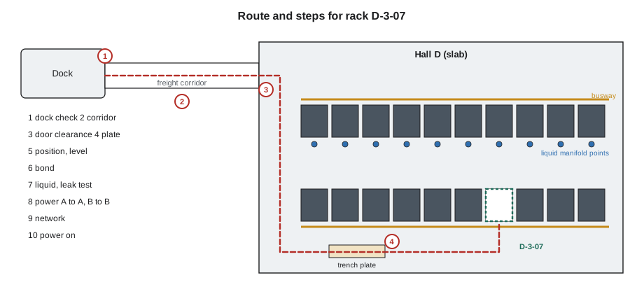
Thursday morning: receiving
The truck arrives at 7:10 with two racks, D-3-07's and D-3-08's, each strapped upright on an air-ride trailer. Tomás and Jamal meet it with the integrator's crew. Jamal checks both racks' shock and tilt indicators before anything is unstrapped. D-3-07's are clean. On D-3-08, one shock indicator has turned red. Jamal photographs it, Tomás notes it on the delivery receipt before signing, and Carmen decides that D-3-08 will be inspected by the integrator before it goes any further. It waits in the receiving bay, under camera, while the work on D-3-07 continues. The serial numbers and asset tags of both racks are recorded against the receiving ticket.
The move
The integrator's crew brings D-3-07 off the trailer on the dock leveller and onto its moving skates; the rack's own casters are not rated for the full rolling load over the route. The crew has four people: two pushing at the rear, one guiding at the front and a spotter. Jamal walks ahead as the Stonebridge spotter, opening and holding each door and clearing the route, and he has the stop call as well. They move slowly. At the Hall D door Jamal watches the top of the rack clear the frame with its few centimetres to spare. The load-spreading plate is in place over the trench cover. The move from dock to position takes thirty-five minutes. Nobody touches the rack's doors, which are strapped shut.
Positioning, levelling and bonding
At D-3-07, the crew aligns the rack with its neighbours, front to the cold side of the row, and lowers its levelling feet until the skates can be removed and the feet carry the weight. Jamal checks it with a level front to back and side to side, and finds it within the integrator's tolerance. He connects the rack's bonding conductor to the row's ground bar and checks it is tight, then fits the baying hardware to its neighbour and the containment panels above it. He records the position in DCIM and fits the cabinet identifier labels, front and rear.
Liquid connection and leak test
Liquid work is done by the integrator under the MOP, with Stonebridge's facilities technician present, because the manifold valves belong to Stonebridge's cooling system. The integrator connects the rack's supply and return hoses to the manifold's quick disconnects, checks every connection by hand and by a pull test, and fills and vents the rack's loop. The facilities technician opens the manifold valves slowly while everyone watches the leak detection cable that runs under the rack and the connections themselves. The loop is held at pressure and checked for drops over the agreed time. Jamal's job is to watch, to record each check against the MOP, and to make sure the leak detection alarm for D-3-07 is live in the monitoring system before the valves open. No leak is found.
Power connection
With the liquid loop proven, the integrator connects the rack's power inlets to the D-3-07 tap-offs, which are still switched off. Jamal checks that each connector is fully seated and latched, that the A-side inlets go to A-side tap-offs and the B-side inlets to B-side tap-offs, matching their colour-coded labels, and that the inlet cables are routed and supported as the MOP describes. The facilities electrician then switches the tap-offs on, one at a time, and reads the voltage at each before the next. The rack's power shelves come up and report their status. The rack itself is not powered on yet.
Network
Corvid's network engineers connect the rack's optical links to the overhead fibre trays: dozens of high-speed connections, each with its own label at both ends. Stonebridge's part is the pathway and the labels on the trays; the transceivers and their connections are Corvid's. Jamal checks that every cable leaving the rack is supported in the tray, that nothing crosses the hot side's exhaust area, and that no cable is bent tighter than its minimum radius where it turns into the tray.
Power on and acceptance
At 13:20 Carmen gives the go to power on. The rack's management controllers start first, then its compute trays, in the order the integrator's procedure sets. Jamal watches the busway tap-off readings rise and the coolant temperatures from the manifold settle as the load comes on. At full test load, the rack draws close to its expected power, its coolant return temperature sits within the design range, and the cold-side temperature in front of it is unchanged. Carmen runs Corvid's acceptance tests for the rest of the afternoon and accepts the rack at 17:40.
# Installation record for rack D-3-07: every MOP step signed before the next
steps = [
    ("Receiving: indicators clean, serials and asset tag recorded", "JP"),
    ("Route walked; trench plate in place; doors held", "JP"),
    ("Positioned, level within tolerance, skates removed", "Integrator / JP"),
    ("Bonding connected and tight; baying and containment fitted", "JP"),
    ("Leak detection live; loop filled, valves opened, pressure held", "Integrator / Facilities"),
    ("Power inlets connected A to A and B to B; tap-offs energized one by one", "Integrator / Electrician"),
    ("Optical links in tray, labelled both ends", "Corvid / JP"),
    ("Powered on; load and coolant temperatures normal", "Corvid"),
    ("DCIM: position, weight, power, liquid and network records complete", "JP"),
]
for n, (text, who) in enumerate(steps, 1):
    print(f"{n}. [signed {who}] {text}")
print("Rack D-3-07 accepted by Corvid AI; ticket closed with photographs and the signed MOP")1. [signed JP] Receiving: indicators clean, serials and asset tag recorded 2. [signed JP] Route walked; trench plate in place; doors held 3. [signed Integrator / JP] Positioned, level within tolerance, skates removed 4. [signed JP] Bonding connected and tight; baying and containment fitted 5. [signed Integrator / Facilities] Leak detection live; loop filled, valves opened, pressure held 6. [signed Integrator / Electrician] Power inlets connected A to A and B to B; tap-offs energized one by one 7. [signed Corvid / JP] Optical links in tray, labelled both ends 8. [signed Corvid] Powered on; load and coolant temperatures normal 9. [signed JP] DCIM: position, weight, power, liquid and network records complete Rack D-3-07 accepted by Corvid AI; ticket closed with photographs and the signed MOP
Afterwards
The next morning the integrator inspects D-3-08, the rack whose shock indicator had tripped. They find a cracked bracket on one of its internal coolant manifolds, which would have leaked once the loop was filled. The rack goes back to the plant and a replacement arrives the following week. Roz points out to Jamal that his inspection at the dock, a few seconds with a photograph and a note on the receipt, may have prevented a coolant leak inside a fully powered AI rack in the middle of Hall D, and certainly made the warranty claim simple.
Over the next three weeks the other six racks follow the same MOP. By the fourth, the installation takes half a day. The steps do not get shorter, but everyone knows them, and every check from this course is in them: receive and inspect, plan the route, respect the ratings, position and level and bond, connect power A to A and B to B, keep the air and liquid paths tight, label everything, record everything, and stop whenever something does not match.
Worked problem
A mismatch at the tap-off
On the fifth rack, at D-3-11, Jamal finds while checking the power connections that one of the rack's B-side inlets has been connected to an A-side tap-off. The tap-offs are still switched off.
Show solution
- Stop the step under the MOP: power is not to be switched on with a mismatch.
- Show the integrator's lead the labels on the inlet and the tap-off, and photograph both.
- The integrator moves the inlet to the correct B-side tap-off.
- Recheck every connection on the rack against its labels before signing the step, and note the correction in the record.
Answer: The mismatch would not have stopped the rack from running, but it would have put two of its feeds on the same side of the power system, so that maintenance on the A side would have taken away more of its power than the design allowed. Caught before power-on, it cost five minutes.
Common mistakes
MistakeTreating an integrated rack like a heavy cabinet.
InsteadFollow a written MOP with the integrator and customer, step by step.
MistakeSigning for a rack whose shock indicator has tripped without noting it.
InsteadNote and photograph it, and hold the rack for inspection.
MistakeRolling a heavy rack on its own casters over the whole route.
InsteadUse rated skates and protect trench covers and floor boxes.
MistakeOpening liquid valves before leak detection is live.
InsteadConfirm the alarm is live, then open valves slowly and watch.
MistakeEnergizing power with any connection unchecked.
InsteadCheck every inlet against its tap-off label, A to A and B to B, before switching on.
Summary and key terms
- AI racks arrive integrated, very heavy, liquid-cooled and power-dense; work on them follows a written MOP.
- Receiving inspections and indicators matter; a tripped indicator holds the rack for inspection.
- Plan the route, the floor and the position in detail, and use rated moving equipment.
- Position, level, bond and record before any connection is made.
- Liquid connections are leak-tested with detection live before power is connected.
- Power is connected A to A and B to B, checked, then energized one feed at a time, before power-on and acceptance.
- Integrated rack
- A rack built, cabled and tested at the factory and shipped whole.
- Method of procedure (MOP)
- A step-by-step script for high-risk work, with checks, roles and stop points.
- Quick disconnect
- A coupling that connects and disconnects a liquid hose without spilling coolant.
- Power shelf
- A unit in an AI or Open Rack that converts incoming power for the rack's busbar.
- Leak detection cable
- A sensing cable laid under liquid-cooled equipment that alarms when wet.
- Acceptance
- The customer's confirmation that installed equipment works as specified.
Practice problems
Work each problem on paper first, then reveal the answer to check.
Why was rack D-3-08 held at the dock?
Show answer
One of its shock indicators had tripped, so the integrator inspected it before installation.
Why must leak detection be live before the manifold valves open?
Show answer
So that any leak at the new connections is detected at once.
What was wrong at D-3-11, and why did it matter?
Show answer
A B-side inlet was on an A-side tap-off; maintenance on the A side would have removed more of the rack's power than the design allowed.
Name four checks from earlier lessons that the MOP contains.
Show answer
Any four of: receiving inspection, route and floor ratings, positioning and levelling, bonding, A and B power, airflow and containment, labels both ends, DCIM records.
Lesson quiz · 5 questions
Score 60% or more to complete this lesson.
Create a free account to save your progress, take quizzes and earn a certificate.