
DCE-499 · Lesson 9 of 12 · 24 min
Network and cabling concept
A data centre exists to connect computing to users and to other computers, so its network infrastructure is as critical as its power and cooling. For a colocation and cloud campus such as Aurora, the network design must provide diverse, high-capacity connections to carriers and cloud on-ramps, flexible interconnection between customers in meet-me rooms, structured cabling that can be extended as halls fill, and, for AI clusters, extremely dense fabrics with hundreds of thousands of fibres between racks. The facility designer does not usually choose customers' switches and servers, but must provide the spaces, pathways, cabling plant and power that their networks need, and must anticipate the very different requirements of enterprise and AI deployments. This lesson covers carrier entrances and meet-me rooms, the ANSI/TIA-942 space hierarchy, pathways, cabling media, AI backend fabrics and their fibre counts, labelling and testing, and the coordination between network design and the other disciplines.
Carrier entrances and meet-me rooms
Fibre from carriers enters the campus through underground duct banks to entrance rooms. For resilience, Aurora provides at least two entrance points on opposite sides of the campus, with diverse duct routes that do not share trenches or bridges, leading to two separate meet-me rooms (MMRs) in each building. Carriers place their equipment in the MMRs, and customers connect to carriers and to each other through cross-connects: fibre patch connections managed by the operator. Meet-me rooms are revenue-generating spaces for colocation operators, and their design must allow for growth in carriers and cross-connects, secure access for carrier technicians, redundant power and cooling, and clean agent fire protection (Lesson 8).
Design decisions include the number and size of entrance ducts (with spares for future carriers), the size of MMRs and cross-connect frames, pathways from MMRs to every data hall, and whether to provide dedicated cloud on-ramp spaces for hyperscale cloud providers' direct connection equipment.
The TIA-942 space hierarchy
ANSI/TIA-942 defines functional spaces for data centre cabling, which help organize the design:
- Entrance room (ER): where carrier cables enter and demarcate.
- Main distribution area (MDA): the central point of the cabling system, housing core routers and switches and the main cross-connect.
- Intermediate distribution area (IDA): an optional level in large facilities.
- Horizontal distribution area (HDA): serving a group of rows, with distribution switches and the horizontal cross-connect.
- Zone distribution area (ZDA): an optional consolidation point within rows.
- Equipment distribution area (EDA): the racks and cabinets housing servers.
Modern designs often place network equipment at the top or end of each row (top-of-rack or end-of-row) rather than in separate HDAs, but the hierarchy still guides cabling plans. TIA-942 also defines rated levels for infrastructure resilience, comparable in intent to other tier frameworks.
In Canada, CSA Group publishes Canadian adoptions of many TIA cabling standards, and the Canadian Electrical Code governs communications cable listings and installation in Section 60, including requirements for plenum and riser ratings.
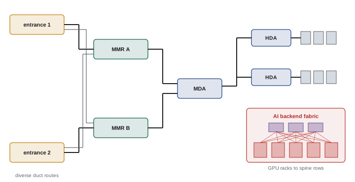
Pathways
Cabling pathways must carry today's cables and tomorrow's, without compromising cooling, power or fire protection. In slab-on-grade halls without raised floors, overhead cable trays or baskets are standard, typically in layered levels: power busway at one level, fibre trays at another, and copper trays at a third, with clear separation and coordinated heights over hot and cold aisles. Pathway fill should be limited (often to about 40 % to 50 % of tray capacity at design) to leave room for growth and to avoid crushing cables. Dedicated fibre raceway systems with protected bend radii carry high-count trunks. Pathways crossing fire separations need listed firestop systems that can be reopened for new cables. Liquid cooling adds piping overhead or below racks, which must be coordinated with cable trays so leaks cannot drip onto cables and connectors.
Cabling media
Data centre cabling uses three main media:
- Singlemode fibre (OS2): used for links between buildings, to carriers, and increasingly within data centres for high-speed links (400G and 800G optics such as DR4 and DR8 use parallel singlemode fibres). It supports long distances and future speeds.
- Multimode fibre (OM4, OM5): used for short links within rows and halls, with lower-cost optics, but limited distances at high speeds.
- Copper: direct-attach copper cables (DACs) and active electrical cables (AECs) for very short in-rack and adjacent-rack links, and twisted-pair Category 6A cabling for management networks and building systems.
High-density connectivity relies on MPO/MTP multi-fibre connectors (12, 16 or 24 fibres), pre-terminated trunk cables, and high-density patch panels. Very high fibre count trunks, with thousands of fibres in a single cable using ribbon technology, connect large fabrics across halls.
AI backend fabrics
AI training clusters use a separate high-performance backend network that connects every accelerator to every other, in addition to the front-end network that connects servers to storage and users. Backend fabrics are typically non-blocking, use the fastest available links (currently 400G and 800G per port, moving to 1.6T), and are arranged as multi-tier fat trees or rail-optimized topologies. Their size and fibre counts dwarf traditional networks, and they impose strict limits on cable lengths for latency and optics reach, which in turn constrain where racks and switch rows can be placed.
import math
# Sizing the backend fabric for an AI cluster in the liquid-cooled halls
racks = 144
gpus_per_rack = 72
k = 64                        # 51.2 Tb/s switch with 64 ports of 800G
gpus = racks * gpus_per_rack  # one 800G backend port per GPU

two_tier_max = k * k // 2
print(f"GPUs {gpus:,}; largest non-blocking two-tier fabric: {two_tier_max:,} GPUs")
if gpus > two_tier_max:
    print("two tiers are not enough, so use a three-tier fat tree built from pods")

per_pod = (k // 2) ** 2               # 32 leaves x 32 GPUs each
pods = math.ceil(gpus / per_pod)
leaves = pods * k // 2
spines = pods * k // 2
links_leaf_spine = leaves * k // 2
super_spines = math.ceil(spines * k // 2 / k)
links_spine_super = spines * k // 2
print(f"pods {pods}; leaves {leaves}; spines {spines}; super spines {super_spines}")
print(f"switches in total {leaves + spines + super_spines}")

fibers_per_link = 16                  # 800G DR8 optics: 8 transmit and 8 receive fibers
trunk_fibers = (links_leaf_spine + links_spine_super) * fibers_per_link
print(f"switch to switch links {links_leaf_spine + links_spine_super:,}, fibers {trunk_fibers:,}")
print(f"equivalent to {math.ceil(trunk_fibers / 3456)} trunk cables of 3,456 fibers")GPUs 10,368; largest non-blocking two-tier fabric: 2,048 GPUs two tiers are not enough, so use a three-tier fat tree built from pods pods 11; leaves 352; spines 352; super spines 176 switches in total 880 switch to switch links 22,528, fibers 360,448 equivalent to 105 trunk cables of 3,456 fibers
The calculation shows why AI fabrics drive facility design. With 64-port switches, a two-tier fabric can support only about 2,000 GPUs without oversubscription, so the 10,000-GPU cluster needs three tiers: 11 pods, 880 switches and over 22,000 switch-to-switch links using more than 360,000 fibres. That is equivalent to over a hundred of the largest trunk cables. The facility must provide pathways for this volume of fibre, rows of network racks positioned to keep link lengths within optic reach, power and cooling for hundreds of switches (each drawing perhaps 2 kW or more), and installation time in the schedule: terminating and testing hundreds of thousands of fibres takes weeks of skilled labour.
Labelling, documentation and testing
With hundreds of thousands of connections, documentation is critical. ANSI/TIA-606 defines administration standards for labelling cables, panels, ports and pathways with unique identifiers, and records linking each connection end to end. Many operators use database or DCIM tools to manage cabling records (Lesson 10). Every installed fibre link is tested before handover: Tier 1 testing with an optical loss test set measures insertion loss against a budget calculated from the standard, and Tier 2 testing with an OTDR locates and characterizes connectors, splices and faults. Connector end-face inspection and cleaning are essential, since contamination is the leading cause of fibre link failures, especially for high-speed singlemode optics with tight loss budgets.
Worked problem
Checking a fibre link loss budget
A 400 m singlemode link between a leaf row and a spine row has two MPO connections (0.35 dB each as a design allowance) and one fusion splice (0.1 dB). Fibre attenuation is 0.4 dB/km at 1310 nm. The optics allow a maximum channel insertion loss of 3.0 dB. Does the link meet the budget?
Show solution
- Fibre loss: 0.4 km × 0.4 dB/km = 0.16 dB.
- Connector loss: 2 × 0.35 = 0.70 dB.
- Splice loss: 0.10 dB.
- Total: 0.16 + 0.70 + 0.10 = 0.96 dB, well within 3.0 dB.
Answer: The link meets the budget with about 2 dB of margin. Adding cross-connects or patch panels would add 0.35 to 0.75 dB each, so margin should be checked whenever the channel design changes.
Coordination with other disciplines
Network design touches every other discipline. Electrical design must provide power to network racks and MMRs with appropriate redundancy. Mechanical design must cool network switches, which often have front-to-back or back-to-front airflow that must match the aisle arrangement. Structural design must carry the weight of cable trays filled with fibre, which can be substantial. Architectural design must provide secure, separate access for carriers. Fire protection must protect MMRs and seal pathway penetrations. And the schedule must allow time for installing and testing the cabling plant after the white space is ready but before customers move in.
Planning for growth and change
Networks change more often than any other data centre system. Customers add cross-connects weekly, AI clusters are reconfigured as new generations of accelerators arrive, and link speeds roughly double every few years. The cabling concept should therefore favour structured, modular cabling over point-to-point connections, pre-terminated trunks that can be installed quickly, spare capacity in pathways and in meet-me room frames, and singlemode fibre for backbone links so that future optics can reuse the plant. Documentation and change processes must keep up with this pace; outdated cabling records are a common source of errors during moves and changes.
The design should also consider how new network hardware will be installed. AI clusters are often delivered as complete racks pre-cabled at the factory, which arrive on pallets and must be moved through the building, connected to power, liquid cooling and network trunks, and tested within days. Docks, corridors, staging areas and installation procedures must support this rapid deployment.
Finally, the network concept should state who owns and operates each part of the cabling plant: the operator typically owns the backbone, meet-me room frames and pathways, while customers own the cabling within their cages and their own fabrics. Clear demarcation avoids disputes during moves and troubleshooting.
In the capstone, the network concept should include a schematic of carrier entrances and meet-me rooms, a pathway plan for one data hall, fibre counts for the AI fabric and the colocation backbone, and a short statement of the standards and testing requirements that will apply.
Common mistakes
MistakeRunning both carrier routes through the same trench.
InsteadProvide physically diverse entrances and routes.
MistakeFilling cable trays to capacity at handover.
InsteadDesign for about 40 to 50 % fill to allow growth.
MistakeUnderestimating AI fabric fibre counts.
InsteadSize pathways from fabric calculations.
MistakeSkipping end-face inspection.
InsteadInspect and clean every connector before testing.
MistakeRouting liquid cooling pipes above fibre trays without protection.
InsteadCoordinate levels and provide drip protection.
Summary and key terms
- Diverse carrier entrances and two meet-me rooms per building provide resilient connectivity.
- TIA-942 defines spaces from entrance rooms and MDA to HDA, ZDA and EDA.
- Overhead pathways are layered for power, fibre and copper, with room for growth.
- Singlemode fibre dominates high-speed links; MPO connectors and high-count trunks provide density.
- AI backend fabrics need multi-tier designs, hundreds of switches and hundreds of thousands of fibres.
- TIA-606 labelling, loss testing, OTDR testing and connector cleaning ensure quality.
- Network design must be coordinated with power, cooling, structure, security and schedule.
- Meet-me room
- A space where carriers and customers interconnect.
- Cross-connect
- A patch connection between two parties' cabling.
- Main distribution area
- The central cabling space in TIA-942.
- Equipment distribution area
- The racks housing servers and storage.
- Pathway fill
- The proportion of tray capacity occupied by cables.
- Singlemode fibre
- Fibre with a small core for long-distance, high-speed links.
- MPO connector
- A multi-fibre push-on connector.
- Backend fabric
- The high-performance network linking AI accelerators.
- Fat tree
- A multi-tier non-blocking network topology.
- Insertion loss
- The optical power lost across a link.
Practice problems
Work each problem on paper first, then reveal the answer to check.
Why provide two entrance rooms on opposite sides?
Show answer
So a single cable cut or excavation does not isolate the campus.
What happens in a meet-me room?
Show answer
Carriers and customers interconnect through cross-connects.
List the TIA-942 spaces.
Show answer
ER, MDA, IDA, HDA, ZDA, EDA.
What tray fill is typical at design?
Show answer
About 40 to 50 %.
Why is singlemode fibre increasingly used inside data centres?
Show answer
High-speed parallel optics such as DR4 and DR8 use it.
What is the largest non-blocking two-tier fabric with 64-port switches?
Show answer
2,048 endpoints.
How many fibres does an 800G DR8 link use?
Show answer
16.
What is the leading cause of fibre link failures?
Show answer
Contaminated connector end faces.
Compute loss: 0.8 km at 0.4 dB/km, 4 connectors at 0.35 dB.
Show answer
0.32 + 1.4 = 1.72 dB.
Name three disciplines affected by network design.
Show answer
Electrical, mechanical, structural, architectural, fire protection.
Lesson quiz · 5 questions
Score 60% or more to complete this lesson.
Create a free account to save your progress, take quizzes and earn a certificate.