
DCE-499 · Lesson 4 of 12 · 24 min
Defining the load: IT capacity, densities and the energy model
Every system in a data centre is sized from the IT load: how much power the servers, storage and network equipment will draw, how densely it will be packed, how it will be cooled, and how it will vary over time. Getting the load definition wrong is one of the most expensive mistakes in data centre design. Overestimate it and the owner pays for idle transformers, generators and chillers; underestimate it, or misjudge the mix of air and liquid cooling, and the facility cannot host the customers it was built for. The rapid rise of AI hardware, with racks drawing ten times the power of traditional enterprise racks and loads that swing sharply within seconds, has made load definition harder and more important. This lesson covers the definitions of IT capacity, rack density and the air-liquid split, the dynamic behaviour of AI loads, data hall planning, the efficiency metrics PUE and WUE, and an energy model for phase 1 of Aurora.
Defining IT capacity
Several numbers describe IT load, and confusing them causes design errors:
- Design or critical IT capacity: the maximum IT power the infrastructure is designed to support continuously with the required redundancy, for example 24 MW per phase at Aurora. This is the basis for sizing UPS, distribution and cooling.
- Contracted or sold capacity: the power customers have reserved. Operators sometimes sell slightly more than design capacity because customers rarely use their full reservation at once, but doing so requires good monitoring and careful risk management.
- Nameplate power: the maximum rating printed on server power supplies, usually well above actual use. Designing from nameplate overstates load significantly.
- Measured or operating load: what the IT equipment actually draws, which varies with utilization and over time.
The design capacity should be defined at the point where it is measured, usually at the output of the UPS or at the rack power distribution units, and the basis of design should state clearly whether it includes network rooms, meet-me rooms and other support spaces.
Rack density and the air-liquid split
Rack density, the power per rack, determines how many racks fit in a hall, how they must be cooled, and how power is distributed to them. Traditional enterprise and colocation racks average perhaps 5 to 15 kW. High-performance computing and AI racks are far denser: racks of current AI accelerators commonly draw 40 to 130 kW, and vendors have announced platforms exceeding several hundred kilowatts per rack. Air cooling becomes impractical above roughly 30 to 50 kW per rack, so dense racks use direct-to-chip liquid cooling, rear-door heat exchangers or immersion cooling (Lesson 6).
The Aurora brief leaves the split between air-cooled colocation and liquid-cooled AI uncertain. A sound design handles this uncertainty with flexibility: data halls that can be fitted out for either, cooling plants that can deliver both chilled water for air handlers and warmer water for liquid cooling, electrical distribution that can serve both low- and high-density rows, and structural floors rated for heavy liquid-cooled racks throughout. The base case for phase 1 assumes 40 % air-cooled and 60 % liquid-cooled IT load.
import numpy as np
# Phase 1 load model: racks, monthly PUE and annual energy for a cool climate
it_mw = 24.0
air_share = 0.40
air_kw_rack, liquid_kw_rack = 12, 100
air_mw, liquid_mw = it_mw * air_share, it_mw * (1 - air_share)
print(f"air-cooled IT {air_mw:.1f} MW = {air_mw * 1000 / air_kw_rack:.0f} racks at {air_kw_rack} kW")
print(f"liquid-cooled IT {liquid_mw:.1f} MW = {liquid_mw * 1000 / liquid_kw_rack:.0f} racks at {liquid_kw_rack} kW")

temps = np.array([-12, -9, -3, 5, 12, 17, 20, 19, 13, 6, -2, -9])   # monthly mean dry bulb, C
hours = np.array([744, 672, 744, 720, 744, 720, 744, 744, 720, 744, 720, 744])

def cooling_fraction(t, kind):
    # cooling power as a fraction of IT power, rising with outdoor temperature
    base, slope, free_limit = (0.10, 0.010, 10) if kind == "air" else (0.05, 0.005, 22)
    return base + slope * max(0, t - free_limit) + (0.0 if t < free_limit else 0.02)

def pue(t, util):
    it = it_mw * util
    cool = air_mw * util * cooling_fraction(t, "air") + liquid_mw * util * cooling_fraction(t, "liquid")
    fixed = 1.0                        # MW of lighting, offices, controls, transformer no-load losses
    losses = 0.05 * it                # UPS and distribution losses
    return (it + cool + fixed + losses) / it

for util in (1.0, 0.5):
    p = np.array([pue(t, util) for t in temps])
    it_energy = it_mw * util * hours.sum()
    annual = (p * it_mw * util * hours).sum() / it_energy
print(f"utilization {util:.0%}: monthly PUE {p.min():.3f} to {p.max():.3f}, annualized {annual:.3f}, facility energy {annual * it_energy / 1000:,.0f} GWh")air-cooled IT 9.6 MW = 800 racks at 12 kW liquid-cooled IT 14.4 MW = 144 racks at 100 kW utilization 100%: monthly PUE 1.162 to 1.210, annualized 1.175, facility energy 247 GWh utilization 50%: monthly PUE 1.203 to 1.251, annualized 1.217, facility energy 128 GWh
Dynamic AI loads
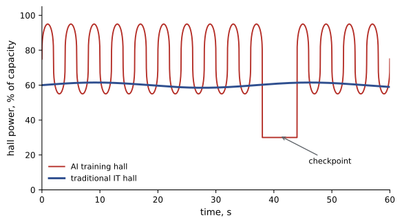
AI training clusters behave differently from traditional IT. Thousands of accelerators run synchronized workloads that alternate between computation and communication phases, so the power of an entire hall can swing by a large fraction of its peak within a fraction of a second, repeating many times a minute. Checkpointing and job start or stop events cause larger steps. These swings affect the whole power chain:
- UPS systems must handle rapid load steps without transferring to bypass or tripping.
- Generators must accept large load steps and rejections during outages; diesel engines have limits on how fast they can pick up load without frequency dips.
- Utilities and grid operators are concerned about oscillating loads of tens or hundreds of megawatts, which can interact with grid stability, and some now require large loads to demonstrate ride-through capability and limits on the rate of change of power.
- Cooling systems see rapid changes in heat load, which liquid systems must absorb without temperature excursions at the chips.
Mitigations include energy storage at the rack, row or facility level to smooth the load, software power capping and job scheduling coordinated with facility operators, and UPS and generator specifications that include AI load profiles. The basis of design should state the assumed load dynamics so that each discipline designs to them.
Data hall planning
Data halls are typically sized as repeatable modules, each served by its own electrical and mechanical blocks, so the design can be replicated across phases. For Aurora, the team considers halls of 6 MW each, giving four halls per phase. Hall dimensions follow from the rack count, row layout, aisle widths, cooling equipment positions, and space for power distribution. Air-cooled halls of 12 kW racks need much more floor area per megawatt than liquid-cooled AI halls, where the floor is often dominated by coolant distribution units (CDUs), piping and power distribution rather than racks.
Worked problem
Sizing a data hall
An air-cooled 6 MW hall uses 12 kW racks in rows of 20 racks. Each rack occupies a footprint of 0.6 m by 1.2 m, and a row pair with hot and cold aisles needs about 3.6 m of depth per row plus aisle share. Estimate the number of racks, rows and the white space area if each row with its share of aisles occupies about 12 m by 3.6 m and circulation and equipment add 40 %.
Show solution
- Racks: 6,000 kW ÷ 12 kW = 500 racks.
- Rows: 500 ÷ 20 = 25 rows.
- Row area: 25 × 12 m × 3.6 m = 1,080 m².
- Add 40 % for perimeter cooling units, power distribution and circulation: 1,080 × 1.4 = 1,512 m².
- Power density: 6,000 kW ÷ 1,512 m² ≈ 4.0 kW/m², roughly 370 W/ft².
Answer: About 500 racks in 25 rows on roughly 1,500 m² of white space. A liquid-cooled 6 MW hall with 100 kW racks would have only about 60 racks but would need space for CDUs and heavier floors.
Efficiency metrics
Power usage effectiveness (PUE) is the ratio of total facility energy to IT equipment energy, defined in ISO/IEC 30134-2. A PUE of 1.25 means that for every 1 kWh delivered to IT, 0.25 kWh is used by cooling, power losses, lighting and other overheads. PUE should be stated as an annualized value based on energy over a year, because instantaneous PUE varies with weather and load. Design PUE at full load in mild weather is always better than annualized PUE at partial load, so the client and design team must agree which value is meant.
Water usage effectiveness (WUE), defined in ISO/IEC 30134-9, is the annual site water use for cooling and humidification divided by the IT energy, in litres per kWh. Evaporative cooling designs may have WUE around 1 to 2 L/kWh in warm climates, while air-cooled and dry-cooled designs can approach zero on-site water use, at the cost of higher energy use. Other metrics include carbon usage effectiveness (CUE) and energy reuse effectiveness (ERE), which credits heat exported for reuse (Lesson 12).
The energy model shows two important effects. First, a liquid-heavy design in a cool climate can achieve an annualized PUE below 1.2 at full load, comfortably meeting the 1.25 target. Second, at half utilization, which is realistic during the first years of the ramp, PUE rises because fixed losses (lighting, controls, transformer no-load losses) and partly loaded equipment are spread over less IT energy. Designs that perform well at partial load, through modular plant that can be staged and variable-speed equipment, protect efficiency during the long ramp-up.
Load growth and design margins
Engineers apply margins to account for uncertainty, but stacking margins in every discipline leads to oversized, inefficient facilities. Good practice is to agree on a single set of design loads in the basis of design, with explicit allowances for growth and uncertainty, and to avoid each discipline adding its own hidden margin. Where growth is uncertain, modular expansion is usually better than oversizing on day one.
Communicating load assumptions
Because every discipline depends on the load definition, the team should publish it as a single, version-controlled load schedule: IT capacity per hall and per block, the assumed air and liquid split, rack densities and weights, heat rejected to air and to liquid, mechanical loads, and the dynamic load profile assumed for AI halls. When the client revises the customer mix, the load schedule is updated first and every discipline checks its design against the new version. This simple discipline prevents a common failure in which the electrical, mechanical and structural designs are each based on a different version of the load.
Common mistakes
MistakeDesigning from server nameplate ratings.
InsteadDefine design IT capacity at a stated measurement point.
MistakeFixing the air-liquid split permanently.
InsteadDesign flexible halls and plants for a range of mixes.
MistakeIgnoring rapid AI load swings.
InsteadSpecify load dynamics for UPS, generators and grid.
MistakeQuoting design-day PUE as annualized PUE.
InsteadState annualized values at realistic utilization.
MistakeAdding hidden margins in each discipline.
InsteadAgree one set of design loads with explicit allowances.
Summary and key terms
- Design IT capacity, contracted capacity, nameplate and measured load are different numbers.
- Rack density drives cooling method; air is practical to about 30 to 50 kW per rack.
- Aurora phase 1 assumes 40 % air-cooled and 60 % liquid-cooled IT, with flexible halls.
- AI training loads swing rapidly, affecting UPS, generators, grid and cooling.
- Data halls are repeatable modules; liquid halls need fewer racks but more support space.
- PUE and WUE should be stated as annualized values; partial load raises PUE.
- Avoid stacked margins; use explicit allowances and modular growth.
- Critical IT capacity
- The IT power the infrastructure is designed to support.
- Nameplate power
- The maximum rating marked on equipment.
- Rack density
- Power per rack, in kilowatts.
- Direct-to-chip cooling
- Liquid cooling through cold plates on processors.
- Coolant distribution unit
- Equipment that pumps and conditions liquid for IT cooling.
- Load step
- A sudden change in electrical load.
- Power capping
- Software limits on IT power draw.
- PUE
- Total facility energy divided by IT energy.
- WUE
- Annual site water use divided by IT energy.
- Annualized metric
- A value calculated over a full year of energy or water.
Practice problems
Work each problem on paper first, then reveal the answer to check.
Why is designing from nameplate power a mistake?
Show answer
Nameplate ratings are well above actual consumption.
At about what density does air cooling become impractical?
Show answer
About 30 to 50 kW per rack.
How many 100 kW racks make 14.4 MW?
Show answer
144 racks.
Name three effects of AI load swings.
Show answer
UPS load steps, generator acceptance limits, grid stability concerns, cooling transients.
Name two mitigations for AI load swings.
Show answer
Energy storage and power capping or coordinated scheduling.
How many 12 kW racks make a 6 MW hall?
Show answer
500.
Define PUE.
Show answer
Total facility energy divided by IT energy.
Why does PUE rise at partial load?
Show answer
Fixed losses are spread over less IT energy.
A site uses 30 million litres per year for 200 GWh of IT energy. What is the WUE?
Show answer
0.15 L/kWh.
Why avoid hidden margins in each discipline?
Show answer
Stacked margins oversize the facility and reduce efficiency.
Lesson quiz · 5 questions
Score 60% or more to complete this lesson.
Create a free account to save your progress, take quizzes and earn a certificate.