
DCE-499 · Lesson 5 of 12 · 24 min
Electrical concept: from utility to rack
The electrical system is the backbone of a data centre and typically its largest single cost. It must bring tens or hundreds of megawatts from the utility grid, transform it to usable voltages, keep it flowing through utility outages and equipment failures, and deliver it to racks whose density and behaviour are changing rapidly. In the concept stage, the electrical team chooses the utility interconnection arrangement, medium-voltage distribution, the redundancy topology for UPS and generators, the low-voltage distribution to the white space, and the approach to grounding, protection and monitoring. Each choice trades cost, reliability, maintainability, efficiency and flexibility. This lesson develops the electrical concept for Aurora, compares topologies with a reliability calculation, and shows how to size the main equipment blocks.
Utility interconnection
A 48 MW campus (plus mechanical and other loads, for a total demand of perhaps 60 MW) is normally served at transmission or high sub-transmission voltage, commonly 69 kV to 230 kV or higher. The utility or the owner builds a substation on or next to the site with main power transformers stepping down to a medium distribution voltage. For reliability, the substation should be fed by two or more transmission lines from different directions, ideally from different upstream substations, and arranged so that a single line or breaker failure does not interrupt supply: ring bus and breaker-and-a-half arrangements are common. Main transformers are provided with N+1 or 2N redundancy so that the campus can be carried with one transformer out of service.
Ownership matters: if the utility owns the substation, it operates and maintains it, but the owner has less control over maintenance and expansion; if the owner builds and owns it, costs and responsibilities rise, but so does control. Interconnection agreements specify the capacity, protection and metering requirements, power quality obligations and, increasingly, requirements for large loads to ride through grid disturbances without suddenly disconnecting, since the sudden loss of hundreds of megawatts of data centre load can itself destabilize the grid.
Medium-voltage distribution
From the substation, medium-voltage feeders distribute power around the campus to unit substations at each building or block. Common distribution voltages are 12.47 kV to 34.5 kV, chosen to limit current and cable sizes over campus distances. Medium-voltage switchgear in the substation and at each building uses draw-out vacuum breakers with protective relays. Feeders are arranged as dual radial (each block fed from two independent sources), loops, or main-tie-main arrangements so that any feeder or breaker can be maintained without interrupting critical load.
In Canada, medium-voltage campus distribution commonly uses 25 kV or 13.8 kV, with low-voltage distribution at 600 V for mechanical loads and 600 V or 415/240 V for IT, and installations over 750 V must comply with CEC Section 36.
Block architecture and redundancy topologies
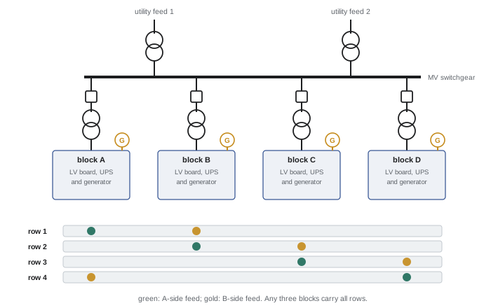
Modern large data centres are built from repeatable power blocks, each sized for a fraction of a data hall (often 1.5 to 3 MW of IT load) and consisting of a unit substation transformer, low-voltage switchboard, UPS, generator and distribution. The topology determines how blocks back each other up:
| Topology | Description | Strengths | Weaknesses |
|---|---|---|---|
| N+1 (block or catcher) | N active blocks plus one reserve block that can be switched to any failed block | Lower cost, high utilization | Transfers needed; shared reserve is a coordination point |
| 2N | Two fully independent systems, each able to carry the whole load | Highest fault tolerance, simple to understand | Highest cost; each system loaded under 50 % |
| Distributed redundant (for example 4N/3) | Four blocks share loads so any three can carry everything | High availability, about 75 % utilization | Complex load assignment and balancing |
| Isolated redundant | Active blocks with a redundant block feeding static transfer switches | Good utilization, isolated failures | Static transfer switches add complexity |
Concurrent maintainability, required by the Aurora brief, means every component can be taken out of service for planned maintenance without interrupting IT load. Fault tolerance goes further: the system continues to supply the load after any single unplanned failure, including during maintenance of another component. Dual-corded IT equipment fed from two independent paths (A and B) is the usual way to achieve fault tolerance at the rack; liquid-cooled AI equipment and single-corded loads may need static transfer switches or rack transfer switches.
Comparing availability
Reliability analysis estimates how often each topology would fail to supply the load. A simple approach uses each component's mean time between failures (MTBF) and mean time to repair (MTTR) to calculate its availability, then combines components according to how many must work.
from math import comb
# Availability of UPS configurations from module reliability (independent failures)
mtbf_h, mttr_h = 100_000, 8
a = mtbf_h / (mtbf_h + mttr_h)          # availability of one UPS module
n = 4                                    # modules needed to carry the load

def k_of_m(k, m, a):
    return sum(comb(m, j) * a ** j * (1 - a) ** (m - j) for j in range(k, m + 1))

bus = 0.999995                           # output switchgear and distribution of one system
configs = {
    "N (4 of 4)": k_of_m(4, 4, a) * bus,
    "N+1 (4 of 5)": k_of_m(4, 5, a) * bus,
    "N+2 (4 of 6)": k_of_m(4, 6, a) * bus,
    "2N (either of two 4-module systems)": 1 - (1 - k_of_m(4, 4, a) * bus) ** 2,
    "distributed redundant 4N/3 (3 of 4 blocks)": k_of_m(3, 4, k_of_m(1, 1, a) * bus),
}
print(f"single module availability {a:.6f}")
for name, av in configs.items():
    minutes = (1 - av) * 525_600
print(f"{name:44s} availability {av:.8f} expected downtime {minutes:8.2f} min/yr")single module availability 0.999920 N (4 of 4) availability 0.99967507 expected downtime 170.79 min/yr N+1 (4 of 5) availability 0.99999494 expected downtime 2.66 min/yr N+2 (4 of 6) availability 0.99999500 expected downtime 2.63 min/yr 2N (either of two 4-module systems) availability 0.99999989 expected downtime 0.06 min/yr distributed redundant 4N/3 (3 of 4 blocks) availability 0.99999996 expected downtime 0.02 min/yr
The results show why topology matters more than adding modules. Moving from N to N+1 reduces expected downtime from hours to minutes per year, but adding a second spare module (N+2) barely helps, because the shared output bus and distribution of a single system become the limiting factor. Only topologies with independent paths, 2N or distributed redundant, remove that single point of failure and reduce expected downtime to seconds. Real analyses use more detailed models (fault trees, Markov models or simulation), include common-cause failures and human error, and account for maintenance states, but the lesson holds: eliminate single points of failure in the distribution, not just in the sources.
UPS and energy storage
Uninterruptible power supplies carry the critical load during the seconds between a utility failure and generator start, and condition power during normal operation. Large data centres mostly use static double-conversion UPS in modular frames, with lithium-ion batteries sized for a few minutes of runtime at full load. Efficiency modes such as eco-mode (bypass with rapid transfer to the inverter) can raise UPS efficiency from about 96 % to 99 %, saving significant energy, but require confidence that the IT equipment and transfer times are compatible. For AI loads, UPS systems must handle rapid load steps (Lesson 4), and some designs add capacitors or batteries close to the racks to smooth fluctuations.
Lithium-ion batteries are compact and long-lived but introduce fire risks such as thermal runaway, so battery rooms need appropriate fire separation, detection and suppression, ventilation and spacing (Lesson 8). Larger battery energy storage systems sized for an hour or more can provide grid services, reduce generator starts, support load smoothing, and potentially allow earlier connection where the utility cannot yet supply full capacity.
Standby generation
Diesel generators remain the standard standby source for data centres because they can carry full load for days given fuel. Each block typically has one generator, with N+1 redundancy at the block or campus level, sized for the IT load plus the mechanical load that must run during outages. Key design decisions include generator ratings (data centre continuous or standby ratings, which differ in allowable running hours), voltage (low- or medium-voltage generators, with medium voltage favoured for large campuses with paralleled plants), fuel storage (often 24 to 72 hours on site, with delivery contracts for longer outages), emissions controls (Lesson 3), noise, and the ability to accept AI load steps. Alternatives such as natural gas reciprocating engines, gas turbines and fuel cells are increasingly considered, sometimes as prime power where grid capacity is delayed.
Worked problem
Sizing a power block
A 6 MW data hall is served by four distributed redundant blocks, any three of which must carry the full hall. Mechanical load that must stay on generator is 25 % of IT load, and the block also carries UPS losses of 4 % and recharge allowance of 5 %. Size the IT capacity per block and the generator per block.
Show solution
- IT per block: 6 MW ÷ 3 = 2 MW, because any three blocks must carry the hall.
- UPS input per block: 2 × (1 + 0.04 + 0.05) = 2.18 MW.
- Mechanical load per block: 0.25 × 2 = 0.5 MW.
- Generator load per block: 2.18 + 0.5 = 2.68 MW; at a power factor of 0.9 this is about 2.98 MVA.
- Select a 3 MW (about 3.75 MVA at 0.8 PF) generator and a 3.5 to 4 MVA unit substation transformer per block.
Answer: Each block supports 2 MW of IT load with a 3 MW generator and a transformer of about 3.5 to 4 MVA. Four blocks serve the 6 MW hall with 75 % utilization under normal operation.
Low-voltage distribution to racks
From each block, power flows through switchboards to busway, power distribution units or remote power panels and then to rack power distribution units. Overhead busway with plug-in units is common because it adapts to changing rack layouts. For dense AI racks, designers consider higher-voltage distribution to the rack (415/240 V or 400/230 V three-phase), larger busway, and direct current architectures such as 48 V or 54 V DC within racks and, increasingly, higher DC voltages (for example ±400 V or 800 V DC) from centralized rectifiers, which reduce conversion losses and copper for very high densities. These choices must be coordinated with the IT equipment the customers will install.
Grounding, protection and monitoring
The electrical concept also defines the grounding system (a site grounding grid connected to building steel, with a signal reference and bonding of all metallic systems), the protection philosophy (coordination studies, arc flash mitigation such as zone selective interlocking and maintenance switches, and arc-resistant switchgear), surge protection, and the electrical power monitoring system (EPMS), which records power quality, events and energy use and integrates with other monitoring (Lesson 10). Early decisions on these matters prevent costly redesigns later.
Coordination points for the electrical concept
The electrical concept must be coordinated with the other disciplines at several points: generator and transformer yard locations with the site plan and noise study; electrical room and battery room sizes with the architectural layout and fire compartments; mechanical loads and their criticality with the mechanical plant; busway and cable tray routes with liquid cooling piping in the white space; and grounding and lightning protection with the structural frame. Early agreement on these interfaces avoids late redesign.
Common mistakes
MistakeAdding UPS modules without removing single points of failure.
InsteadEliminate shared buses with independent paths.
MistakeRelying on a single transmission line.
InsteadSeek two or more independent feeds and a resilient substation.
MistakeSizing generators for IT load only.
InsteadInclude mechanical, UPS losses and recharge.
MistakeIgnoring battery fire risks.
InsteadCoordinate battery rooms with fire protection.
MistakeFixing rack distribution before customers are known.
InsteadDesign flexible busway and voltage options for air and AI racks.
Summary and key terms
- Large campuses connect at transmission voltage through resilient substations with redundant transformers.
- Medium-voltage campus distribution feeds repeatable power blocks.
- Topologies include N+1, 2N, distributed redundant and isolated redundant.
- Reliability analysis shows independent paths matter more than extra modules.
- UPS with lithium-ion batteries bridges to generators; storage can also smooth AI loads.
- Generators are sized for IT, mechanical, losses and recharge, with emissions and fuel planned.
- Distribution to racks must adapt to rising densities, including higher-voltage and DC options.
- Ring bus
- A substation arrangement where breakers form a loop.
- Unit substation
- A transformer with MV and LV switchgear in one assembly.
- Power block
- A repeatable set of electrical equipment serving part of a hall.
- Concurrently maintainable
- Any component can be maintained without interrupting load.
- Fault tolerant
- The load continues after any single unplanned failure.
- Distributed redundant
- A topology where any N of N+1 blocks carry all loads.
- MTBF
- Mean time between failures.
- MTTR
- Mean time to repair.
- Double-conversion UPS
- A UPS that rectifies and re-inverts power continuously.
- Static transfer switch
- A fast electronic switch between two sources.
Practice problems
Work each problem on paper first, then reveal the answer to check.
Why are large campuses connected at transmission voltage?
Show answer
Their demand exceeds what distribution circuits can supply reliably.
Name two resilient substation arrangements.
Show answer
Ring bus and breaker-and-a-half.
Why do grid operators require ride-through from large loads?
Show answer
Sudden loss of large load can destabilize the grid.
Compare 2N and distributed redundant utilization.
Show answer
2N under 50 %; 4N/3 about 75 %.
Define concurrently maintainable.
Show answer
Any component can be maintained without interrupting the load.
Why did N+2 barely improve on N+1 in the calculation?
Show answer
The shared bus remained a single point of failure.
What is eco-mode?
Show answer
UPS operation on bypass with rapid transfer, improving efficiency.
What loads must generators carry?
Show answer
IT, essential mechanical, UPS losses and battery recharge.
A hall of 9 MW uses 4N/3 blocks. What IT capacity per block?
Show answer
3 MW.
Why consider DC distribution for AI racks?
Show answer
Fewer conversion losses and less copper at very high densities.
Lesson quiz · 5 questions
Score 60% or more to complete this lesson.
Create a free account to save your progress, take quizzes and earn a certificate.