
DCE-450 · Lesson 5 of 12 · 26 min
Integrated systems testing
By the time integrated systems testing (IST) begins, every piece of equipment has passed its factory, installation, start-up and functional tests. Yet experience shows that IST still finds serious problems, because it is the first time all the systems are asked to work together, through realistic failures, at full load, with the operations team responding. A generator plant that passed its own tests may not cope with the inrush of every UPS rectifier and chiller at once; a BMS that passed point-to-point checks may flood operators with alarms; a fire alarm interface may shut down equipment it should leave running. This lesson explains what IST is for, how scenarios are chosen, how a test day is run safely, how data are collected and analysed, and what happens when a test fails.
Purpose of integrated testing
IST answers three questions that lower levels cannot. First, do the systems interact correctly? The electrical, mechanical, controls, monitoring, fire and security systems were designed by different engineers, supplied by different vendors and tested separately; IST tests the interfaces between them. Second, does the facility meet its resilience requirements as a whole? A data centre claimed to be concurrently maintainable or fault tolerant must show that it really is. Third, can the people operate it? IST is often the first time the operations team uses its emergency procedures on the real plant, and the observations from test day feed directly into procedures and training (Lesson 9).
Preconditions
IST is expensive and risky, so it does not start until the facility is ready. Typical preconditions are:
- All Level 4 functional tests passed and documented, and all critical and major issues closed.
- Load banks installed throughout the white space to simulate the design IT load, with their power and cooling distribution matching the planned IT layout.
- Final protective device settings verified, controls sequences frozen, and all temporary construction power and overrides removed.
- Fire alarm and suppression systems commissioned and their interfaces to mechanical and electrical systems ready for testing.
- Time-synchronized data collection running on every system: EPMS, BMS, UPS and generator controllers, power quality analysers and temperature sensors.
- Operations staff trained, and emergency operating procedures available for use during the tests.
- A test script for every scenario, reviewed and approved by the owner, designers, contractors, vendors and operators.
Choosing scenarios
Scenarios are chosen to exercise the failures the design claims to tolerate, and the maintenance activities it claims to support. They are derived from the owner's project requirements and from a review of the single-line diagrams and mechanical schematics: for each component or path, what happens if it fails, and can it be taken out of service for maintenance with the IT load still running? A typical IST program includes:
- Loss of utility power to the whole site (often called the pull-the-plug test): generators start, transfer, UPS return to normal, chillers restart, and the facility runs on generators for a set period, then retransfers to utility.
- Loss of utility with a generator failing to start or failing under load, testing generator redundancy.
- Failure of a UPS system, a distribution board or a cooling unit during normal operation.
- Maintenance scenarios: isolating each major component (a UPS, a switchboard, a chiller, a pipe section) using the maintenance procedures, confirming the IT load stays powered and cooled, and restoring it.
- Controls and monitoring failures: loss of the BMS server or network, a failed controller, a sensor failing high.
- Fire alarm events: a fire alarm in a data hall and its effect on air handlers, dampers, suppression release and power, verifying that the interfaces do what the fire strategy requires, and no more.
- Combined events: a failure that occurs while the facility is already in a maintenance configuration, if the design claims to tolerate it.
Redundancy claims and their tests
Data centres are often described by a tier or rating, such as the Uptime Institute Tier classification or the ANSI/TIA-942 ratings. A concurrently maintainable facility (Tier III, Rated-3) must allow any component or distribution path to be removed for planned maintenance without affecting the IT load. A fault tolerant facility (Tier IV, Rated-4) must also withstand any single unplanned failure without affecting the IT load, including failures that occur while maintenance is under way in another part of the system, with automatic response rather than operator action.
IST is where these claims are proven. For concurrent maintainability, the team works through a list of every component and path, isolating each in turn using written procedures. For fault tolerance, the team causes failures without warning to the systems (though with full warning to people) and confirms the automatic response. Certification bodies may witness these tests as part of a construction or facility certification.
Running a test day
IST days are carefully choreographed. A test director runs the event from a command post with radio contact to teams stationed at switchgear, UPS rooms, generator yards, the chiller plant, the data halls and the BMS console. Each scenario begins with a briefing covering the steps, the expected responses, the hold points and the abort criteria. Everyone knows who may stop the test and how.
- Hold points are moments where the test pauses so that observers can confirm the system state before continuing.
- Abort criteria define conditions that end the test immediately and return the facility to normal: for example, a rack inlet temperature above 32 °C, a loss of power to any load bank group, any injury or unsafe condition, or any fire alarm not part of the test.
- Restoration steps return the facility to its normal configuration, and the test director confirms the configuration before the next scenario starts.
Most of IST uses load banks, not live IT equipment, so the consequences of a failure are bounded. On expansions of operating facilities, or after major modifications, IST may take place next to live IT load, and the risk assessment and isolation between the test area and the live area become critical. In these cases, many scenarios are rehearsed on paper first, and some are deliberately reduced in scope.
Collecting and analysing data
The value of IST lies in the evidence. Every system records events with timestamps, but those clocks must agree to within a fraction of a second if events from different systems are to be put in order. Before testing, all controllers and recorders are synchronized to a common time source (usually NTP or PTP from the network, or GPS), and the synchronization is checked. After each scenario, the logs are merged into a single sequence of events and compared with the acceptance criteria.
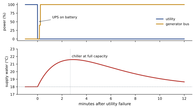
# Integrated systems test: build a sequence of events from time-stamped logs and check criteria
events = [
    ("00:00:00.000", "EPMS", "Utility main breaker opened (test start)"),
    ("00:00:00.004", "UPS-A", "On battery"),
    ("00:00:00.005", "UPS-B", "On battery"),
    ("00:00:01.020", "GEN", "Start signal to all generators"),
    ("00:00:09.400", "GEN", "Generator bus at rated voltage and frequency"),
    ("00:00:11.800", "ATS", "Mechanical load transferred to generator bus"),
    ("00:00:14.100", "UPS-A", "Input restored, walking in rectifier"),
    ("00:00:14.300", "UPS-B", "Input restored, walking in rectifier"),
    ("00:00:31.000", "BMS", "Chiller 1 restart initiated"),
    ("00:02:41.000", "BMS", "Chiller 1 at full capacity"),
    ("00:02:55.000", "BMS", "Peak supply water 21.6 C"),
    ("00:09:30.000", "BMS", "Supply water back to setpoint 18.0 C"),
]

def secs(stamp):
    h, m, s = stamp.split(":")
    return int(h) * 3600 + int(m) * 60 + float(s)

t = {src + ": " + text: secs(stamp) for stamp, src, text in events}
checks = [
    ("Generators ready within 10 s of start signal",
     t["GEN: Generator bus at rated voltage and frequency"] - t["GEN: Start signal to all generators"], 10),
    ("UPS on battery for less than 30 s (last UPS)",
     t["UPS-B: Input restored, walking in rectifier"] - t["UPS-A: On battery"], 30),
    ("Chiller at full capacity within 5 min of outage", t["BMS: Chiller 1 at full capacity"], 300),
    ("Supply water recovered within 15 min", t["BMS: Supply water back to setpoint 18.0 C"], 900),
]
for name, value, limit in checks:
    verdict = "PASS" if value <= limit else "FAIL"
print(f"{name:<48} {value:7.1f} s limit {limit:>4} s {verdict}")Generators ready within 10 s of start signal 8.4 s limit 10 s PASS UPS on battery for less than 30 s (last UPS) 14.3 s limit 30 s PASS Chiller at full capacity within 5 min of outage 161.0 s limit 300 s PASS Supply water recovered within 15 min 570.0 s limit 900 s PASS
In this utility failure test, the generators reached rated voltage and frequency 8.4 seconds after their start signal, the UPS systems were on battery for just over 14 seconds, a chiller reached full capacity 161 seconds after the outage, and supply water recovered to setpoint after 9.5 minutes, all within the criteria. A sequence of events also exposes things the criteria did not anticipate: if the mechanical load had transferred to the generators at the same instant as the UPS rectifiers, the combined step might have exceeded the generators' load acceptance, and the timings show that the controls staggered them.
Worked problem
Diagnosing a test failure
During a pull-the-plug test, generators reach rated voltage at 9 s. At 12 s, all UPS rectifiers begin walking in their load simultaneously, and at the same moment the transfer switches for mechanical load close. Generator frequency dips to 56 Hz (on a 60 Hz system), two UPS units reject the generator input and stay on battery, and an alarm floods the BMS. What happened, and what should change?
Show solution
- The frequency dip to 56 Hz, about 6.7 % below nominal, is larger than the UPS input tolerance, so the rectifiers rejected the input as out of range.
- The cause is the coincidence of the UPS walk-in and the mechanical transfer at the same moment: the combined load step exceeded the generators' load acceptance.
- Two remedies are possible: delay the mechanical transfer by several seconds so the loads arrive in sequence, or lengthen the UPS walk-in time. The controls are changed, the issue is logged, and the scenario is repeated.
Answer: The test failed because of an interaction between correctly functioning systems, which only an integrated test can find. The UPS units still had battery autonomy, so the IT load was never at risk in this test, but the batteries would have been drained in a real event. After the change, the repeat test showed a maximum dip to 58.5 Hz and no rectifier rejections.
When a test fails
A failed IST scenario is not a disaster; finding the failure is the reason for testing. The test director stops the scenario at the abort or hold point, restores the facility, and the team investigates the cause from the sequence of events. The issue goes into the issues log (Lesson 1) with its severity. After the fix, the failed scenario is repeated, and the team considers whether the fix could affect other scenarios already passed, in which case those are repeated too. A common error is to fix a controls problem on the spot and carry on without retesting; the IST record must show a clean pass for every scenario in its final configuration.
Fire and life safety integration
Data centre fire systems interact with almost everything: smoke detection may shut down air handlers or close dampers, gaseous suppression systems need room integrity and may trip equipment before release, and emergency power-off (EPO) controls, where installed, can drop all power to a room. These interfaces are designed according to the fire strategy, and their testing has its own standard.
In Canada, integrated testing of fire protection and life safety systems follows CAN/ULC-S1001, Integrated Systems Testing of Fire Protection and Life Safety Systems, which requires an integrated testing coordinator, a test plan and a report demonstrating that all interconnected systems operate as intended. Fire alarm verification follows CAN/ULC-S537.
The data centre IST and the fire integrated test are planned together, because the fire tests change the state of the mechanical and electrical systems and must not be allowed to interfere with other scenarios or with live load.
After IST
Once every scenario has passed, the commissioning authority prepares the IST report, the facility is returned to its normal configuration, load banks are removed, and the turnover proceeds (Lesson 2). The trend data and sequence-of-events records are kept, because they describe exactly how the facility behaves and are invaluable when investigating a real incident years later (Lesson 11).
Common mistakes
MistakeStarting IST with critical issues still open.
InsteadClose critical and major issues and complete Level 4 before IST.
MistakeCollecting data on unsynchronized clocks.
InsteadSynchronize all recorders to a common time source and check it.
MistakeRunning a scenario without abort criteria.
InsteadDefine abort criteria and who may stop the test before every scenario.
MistakeFixing a problem on the spot and moving on.
InsteadLog the issue, fix it, repeat the scenario and any others affected.
MistakeTesting fire interfaces separately from the IST plan.
InsteadPlan fire integrated testing together with the data centre IST.
Summary and key terms
- IST tests interactions, whole-facility resilience and the operators' response.
- Preconditions include passed functional tests, closed critical issues, load banks and synchronized data.
- Scenarios cover utility loss, equipment failures, maintenance isolations, controls failures and fire events.
- Concurrent maintainability and fault tolerance claims are proven component by component.
- Test days use a director, hold points, abort criteria and restoration steps.
- Merged sequences of events show what happened and are judged against criteria.
- Failed scenarios are fixed and repeated, with any affected scenarios retested.
- Integrated systems testing
- Testing all systems together through realistic failures at load.
- Pull-the-plug test
- A test simulating total loss of utility power.
- Concurrent maintainability
- The ability to maintain any component without affecting IT load.
- Fault tolerance
- The ability to withstand any single failure automatically without affecting IT load.
- Hold point
- A planned pause in a test to confirm system state.
- Abort criteria
- Conditions that end a test immediately.
- Sequence of events
- A time-ordered list of events merged from several systems.
- Time synchronization
- Setting all recorders to a common clock.
- Walk-in
- Gradual ramping of a UPS rectifier's load onto its input source.
- EPO
- Emergency power-off control that de-energizes a room.
Practice problems
Work each problem on paper first, then reveal the answer to check.
Name the three questions IST answers that lower levels cannot.
Show answer
Do systems interact correctly, does the facility meet its resilience requirements, and can the people operate it?
List four IST preconditions.
Show answer
For example: Level 4 passed, critical issues closed, load banks installed, settings verified, data synchronized, operators trained, scripts approved.
What does concurrent maintainability require?
Show answer
Any component or path can be removed for planned maintenance without affecting the IT load.
How does fault tolerance differ?
Show answer
It must also survive any single unplanned failure automatically, even during maintenance.
Give two examples of abort criteria.
Show answer
For example: rack inlet above 32 °C, loss of power to load banks, any injury, an unplanned fire alarm.
Why must clocks be synchronized?
Show answer
To order events from different systems correctly.
From the output, how long were the UPS systems on battery?
Show answer
About 14.3 s.
In the example, why did the UPS units reject the generator input?
Show answer
The frequency dip to 56 Hz exceeded their input tolerance, caused by simultaneous load steps.
What must happen after a failed scenario is fixed?
Show answer
Repeat it, and repeat any other scenarios the fix could affect.
Which standard governs integrated fire and life safety testing in your country?
Show answer
CAN/ULC-S1001.
Lesson quiz · 5 questions
Score 60% or more to complete this lesson.
Create a free account to save your progress, take quizzes and earn a certificate.