
DCE-450 · Lesson 4 of 12 · 26 min
Mechanical and controls commissioning
Every watt delivered to a server becomes heat that must be removed, continuously, or the servers overheat within minutes. The mechanical systems that do this, chillers, cooling towers or dry coolers, pumps, air handlers, coolant distribution units and the controls that run them, are as critical as the electrical system, and they are harder to commission because their behaviour depends on airflow, water flow, temperatures and control loops that interact in complicated ways. This lesson covers how the cooling plant, air systems, liquid cooling, controls and monitoring are commissioned, with particular attention to the moments that cause real outages: equipment failures, restarts after power loss and control instability.
What mechanical commissioning must prove
The owner's project requirements (Lesson 1) usually state the cooling requirement in terms of the IT equipment: for example, server inlet air between 18 °C and 27 °C (the ASHRAE recommended range for most IT equipment), a design IT load per hall, a redundancy level such as N+1 or N+2 for chillers and air handlers, and a maximum time to restore full cooling after a utility failure. Mechanical commissioning must show that the installed systems meet these requirements at design load, at part load (where most data centres operate for years), at the extremes of outdoor weather, and with the redundant components failed.
Testing, adjusting and balancing
Before functional testing, air and water systems are balanced: flows through each coil, air handler, pump and branch are measured and adjusted to the design values. This work, called testing, adjusting and balancing (TAB), is done by certified specialists following procedures from organizations such as AABC or NEBB. Their report lists design and measured flows for every terminal and is an input to commissioning, which checks a sample of the readings independently. Balancing errors cause hot spots and wasted energy for the life of the facility, and they are much easier to correct before the white space fills with racks.
The chilled water or condenser water plant
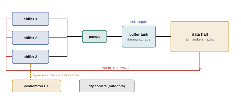
Many data centres use a chilled water plant: chillers cool water, which pumps circulate to air handlers or coolant distribution units in the data halls, while heat is rejected outdoors by cooling towers or dry coolers. In cold climates, economizers bypass the chillers for much of the year, cooling the water with outside air alone. Functional tests of the plant include:
- Staging: as load rises, chillers, pumps and towers are added in the sequence the controls specify; as load falls, they are removed. Tests confirm that staging happens at the right points without temperature swings or cycling.
- Economizer changeover: the transitions between full mechanical cooling, partial economizer and full economizer, which are a common source of instability. Because outdoor conditions cannot be chosen on test day, some sequences are tested by temporarily overriding the outdoor temperature input, and seasonal testing (Lesson 1) completes the record.
- Failure of each component: a chiller trip, a pump failure, a tower fan failure, a valve failing to its safe position, and loss of a controller. Each test verifies that the standby unit starts and that supply temperature stays within limits.
- Restart after power loss: the most demanding test, described below.
Restart after power loss and thermal ride-through
When utility power fails, the UPS carries the IT load immediately, but most chillers are on generator power only and stop until the generators start (typically within 10 to 15 seconds) and the chillers restart. A centrifugal chiller may take several minutes to restart and reach full capacity after a power interruption, unless it has a rapid-restart feature. During that gap, the servers keep producing heat. What carries them through is the cold water already in the pipes and tanks, provided the pumps and air handler fans are on UPS so the water keeps circulating.
The time the stored cold lasts is a simple energy balance: the mass of water times its specific heat times the temperature rise allowed, divided by the heat load.
# Cooling ride-through after chillers stop: how long can stored chilled water carry the IT load?
it_load_kW = 4000          # IT heat load
cp = 4.18                  # kJ/(kg K) for water
loop_volume_m3 = 40        # water in pipes, coils and buffer tanks
tank_m3 = 300              # optional thermal storage tank
supply_C, limit_C = 18.0, 24.0   # chilled water supply now, and highest supply allowed

def ride_through_min(volume_m3):
    energy_kJ = volume_m3 * 1000 * cp * (limit_C - supply_C)
    return energy_kJ / it_load_kW / 60

print(f"Loop only: {ride_through_min(loop_volume_m3):.1f} min")
print(f"Loop plus {tank_m3} m3 tank: {ride_through_min(loop_volume_m3 + tank_m3):.1f} min")

# Chiller restart after a power failure: generator start plus chiller restart time
for restart_s in (60, 180, 300, 600):
    total_min = (15 + restart_s) / 60
    ok = total_min < ride_through_min(loop_volume_m3)
    print(f"Chiller restart {restart_s:>3} s: cooling back after {total_min:4.1f} min; loop alone enough: {ok}")

# Airflow needed by the air handlers for a 10 C air temperature rise across the IT equipment
rho, cp_air, dT = 1.2, 1.006, 10.0
flow = it_load_kW / (rho * cp_air * dT)
print(f"Airflow for {it_load_kW} kW at dT = {dT:.0f} K: {flow:.0f} m3/s")Loop only: 4.2 min Loop plus 300 m3 tank: 35.5 min Chiller restart 60 s: cooling back after 1.2 min; loop alone enough: True Chiller restart 180 s: cooling back after 3.2 min; loop alone enough: True Chiller restart 300 s: cooling back after 5.2 min; loop alone enough: False Chiller restart 600 s: cooling back after 10.2 min; loop alone enough: False Airflow for 4000 kW at dT = 10 K: 331 m3/s
With only the 40 m³ of water in its pipes and coils, the plant can ride through about 4 minutes before supply water exceeds 24 °C. Chillers that restart in one to three minutes are safe; chillers that need five or ten minutes are not, and the servers would see rising inlet temperatures. Adding a 300 m³ thermal storage tank extends the ride-through to over half an hour. The commissioning test, a real power interruption to the plant at design load, proves which case applies: the generators start, the chillers restart, and the trend logs show how high the supply temperature climbed and how long it took to recover. Many owners specify a maximum allowable rise in server inlet temperature during this test.
The same output shows the scale of the air side: 4 MW of IT heat with a 10 K air temperature rise needs over 300 m³/s of air, which is why fan power, airflow paths and containment receive so much attention.
Air systems and containment
Computer room air handlers (CRAHs), fan walls or in-row coolers move air through the IT equipment. Their functional tests cover fan speed control, coil valve control, response to unit failure and the balance between supply airflow and IT airflow. The key concept is that IT equipment draws as much air as its fans demand; if the cooling system supplies less, hot exhaust air recirculates to server inlets; if it supplies much more, fan energy is wasted and cold air bypasses the servers.
Hot aisle or cold aisle containment separates supply and exhaust air, and its effectiveness is tested with load banks distributed across the hall to mimic the planned IT load (Lesson 3). The commissioning team measures:
- Inlet temperatures at the bottom, middle and top of racks across the hall, usually with wireless sensors or a temporary data logger grid, to produce a temperature map.
- Pressure differential between cold and hot aisles, which should be slightly positive on the cold side so that air flows through the equipment rather than around it.
- Response to failure of one air handler: the remaining units should speed up and inlet temperatures should stay within limits.
- Leakage paths: gaps around cable penetrations, missing blanking panels and open containment doors, which show up as hot spots on the temperature map.
Worked problem
Reading a temperature map
During a hall test at 80 % of design load, all rack inlets read 22 to 24 °C except the top of the last three racks at the end of one row, which read 29 °C. Air handler supply is 21 °C and the containment pressure differential averages +3 Pa. What is the likely cause and what should be checked?
Show solution
- The general readings show adequate supply air and positive pressure, so the plant and air handlers are not the problem.
- High inlet temperatures only at the top of end-of-row racks are the classic signature of hot air recirculating over or around the end of the containment.
- Check the end-of-row doors and the roof or ceiling panels of the containment at that end, missing blanking panels in those racks, and whether load banks there are drawing more air than planned.
Answer: Recirculation at the end of the row is most likely. The fix is usually physical (closing a gap or adding blanking panels), followed by a retest to show the inlets fall into range. The issue is logged and closed with the retest data.
Liquid cooling
High-density AI and HPC halls increasingly use direct-to-chip or immersion liquid cooling, served by coolant distribution units (CDUs) that separate the facility water loop from the technology cooling loop at the racks. Commissioning adds steps that air-cooled halls do not need: flushing and filtering new piping until the coolant meets the cleanliness specification (debris can block the fine channels in cold plates), pressure testing every joint, verifying coolant chemistry, testing leak detection along every pipe route, and testing CDU failover so that a pump or CDU failure does not interrupt flow to the chips. Because a direct-to-chip system has very little thermal mass at the chip, flow interruptions of even a few seconds can cause processors to throttle, so failover tests are judged in seconds, not minutes.
Controls and monitoring
Controls commissioning starts with point-to-point verification: every sensor is checked against a reference instrument, and every output is commanded to confirm that the right device responds. A large data centre may have tens of thousands of points across the building management system (BMS), the electrical power monitoring system (EPMS) and the data centre infrastructure management (DCIM) system. Then the sequences of operation are tested: does each control loop do what the written sequence says, in every mode? Trend logging is set up so that every important value is recorded at short intervals during testing and kept afterwards, because the trends are the evidence for the functional tests and the baseline for operations.
Controls also need tests of their own failure modes. What happens when a controller loses power, when the network between controllers fails, when a sensor fails high or low, or when the BMS server is down? A well-designed plant fails safe: valves go to their open position, equipment continues in its last state or a safe default, and local controllers run without the central server. Each of these behaviours must be tested, because they are rarely exercised in normal operation and are often wrong.
Alarms are tested end to end: from the sensor through the controller to the BMS, to the operator console and to any paging or ticketing system. Alarm priorities and settings are reviewed with the operations team, because a system that generates hundreds of minor alarms trains operators to ignore them (Lesson 10).
Codes and standards
In Canada, refrigeration systems are installed and tested to CSA B52, Mechanical refrigeration code, and energy performance is often assessed against the National Energy Code of Canada for Buildings (NECB) or provincial energy codes. Plumbing and pressure piping follow provincial codes and CSA B51 for boiler and pressure vessels where applicable.
Across both countries, the ASHRAE TC 9.9 thermal guidelines define the recommended and allowable temperature and humidity ranges for IT equipment, and they are the usual basis for acceptance criteria.
Common mistakes
MistakeTesting chillers but not the restart after a real power interruption.
InsteadInterrupt power at design load and trend supply temperature until recovery.
MistakeLeaving pumps and air handler fans off UPS.
InsteadKeep circulation running so stored chilled water can carry the load.
MistakeTesting air handlers without realistic heat load in the hall.
InsteadDistribute load banks to mimic planned IT load and map rack inlet temperatures.
MistakeAssuming control failure modes are correct.
InsteadTest loss of controller power, network, sensors and the BMS server.
MistakeFilling liquid cooling loops without flushing.
InsteadFlush and filter to the cleanliness specification before connecting cold plates.
Summary and key terms
- Mechanical commissioning proves cooling at design and part load, in all weather and with redundant units failed.
- Air and water systems are balanced by TAB specialists before functional testing.
- Plant tests cover staging, economizer changeover, component failures and restart after power loss.
- Stored chilled water rides through the chiller restart only if pumps and fans stay on UPS.
- Load banks and temperature maps prove airflow and containment.
- Liquid cooling adds flushing, pressure testing, chemistry, leak detection and fast failover tests.
- Controls need point-to-point checks, sequence tests, failure-mode tests and end-to-end alarm tests.
- TAB
- Testing, adjusting and balancing of air and water flows.
- Staging
- Adding or removing equipment as load changes.
- Economizer
- A mode that cools with outdoor air or water instead of chillers.
- Ride-through
- The time stored cooling carries the load during an interruption.
- Thermal storage tank
- A tank of chilled water that extends ride-through.
- CRAH
- Computer room air handler, using chilled water to cool air.
- Containment
- Physical separation of hot and cold aisles.
- CDU
- Coolant distribution unit serving a liquid cooling loop.
- Point-to-point verification
- Checking each control input and output individually.
- Sequence of operation
- The written description of how a control system behaves.
Practice problems
Work each problem on paper first, then reveal the answer to check.
What is the ASHRAE recommended inlet temperature range for most IT equipment?
Show answer
18 °C to 27 °C.
Why must TAB be done before functional testing?
Show answer
Flows must be correct before system performance can be judged.
Why are economizer changeovers a focus of testing?
Show answer
Transitions between modes are a common source of instability.
Calculate the ride-through of 60 m³ of water allowed to rise 5 K at 3 MW.
Show answer
60,000 × 4.18 × 5 / 3,000 = 418 s, about 7 minutes.
From the output, which chiller restart times are safe with the loop alone?
Show answer
60 s and 180 s; 300 s and 600 s exceed the 4.2-minute ride-through.
What must stay on UPS for the ride-through to work?
Show answer
Chilled water pumps and air handler fans, and their controls.
What does a positive cold aisle pressure differential indicate?
Show answer
Air flows through the IT equipment from cold to hot aisle rather than recirculating.
High inlet temperatures at the top of end racks usually mean what?
Show answer
Hot air recirculating over or around the end of the containment.
Why are liquid cooling failover tests judged in seconds?
Show answer
Cold plates have little thermal mass, so chips throttle quickly when flow stops.
Name three control failure modes to test.
Show answer
For example: controller power loss, network loss, sensor failure, BMS server failure.
Lesson quiz · 5 questions
Score 60% or more to complete this lesson.
Create a free account to save your progress, take quizzes and earn a certificate.