
DCE-200 · Lesson 7 of 12 · 33 min
Networks and connectivity
A data centre without network connections is just an expensive heater. Its value comes from moving data: between servers inside the building, to other data centres, and to the users and businesses it serves. Connectivity shapes where data centres are built, how their buildings are laid out, and how much they are worth: facilities where many networks meet command premium prices, and AI training clusters are limited by how fast their thousands of processors can exchange data. This lesson gives a facility engineer's view of networking: the basic units, the speed of light as a design constraint, how networks are arranged inside the building, how fibre enters and leaves it, and the spaces and pathways that cabling needs. DCE-210 and DCE-320 cover network and cabling design in depth.
Bits, bandwidth and latency
Network capacity (bandwidth) is measured in bits per second: a 100 Gb/s (gigabits per second) link carries 100 billion bits each second, or 12.5 gigabytes per second. Server connections have grown from 1 Gb/s two decades ago to 25, 100, 200 and 400 Gb/s today; switch-to-switch links run at 400 Gb/s and 800 Gb/s, with 1.6 Tb/s arriving. AI servers often have eight network connections of 400 Gb/s or 800 Gb/s each, one per GPU.
Latency is the delay for data to travel from one point to another. Much of it comes from the speed of light in optical fibre, which is about two thirds of its speed in a vacuum, roughly 200,000 km/s, or 5 microseconds per kilometre one way. Round-trip time (RTT) is twice the one-way delay plus processing in switches and routers.
Worked problem
Latency between cities
A fibre route between Toronto and Montréal is about 550 km long. Estimate the one-way and round-trip propagation delays. How far apart could two data centres be if an application needs a round trip under 2 ms?
Show solution
- One way: \(550 \times 5 = 2750\) µs = 2.75 ms; round trip 5.5 ms.
- For a 2 ms round trip: 1 ms one way, so at most \(1000/5 = 200\) km of fibre (less once equipment delays are added).
Answer: About 2.75 ms one way and 5.5 ms round trip. Applications that replicate data synchronously between two sites, such as some financial and database systems, need sites within about 100 km to 200 km of fibre, which is why data centres for one region cluster together, while backup sites can be farther away.
Why location and connectivity go together
Latency and connectivity explain several patterns in where data centres are built:
- Interconnection hubs: certain cities and buildings host many carriers, cloud providers and internet exchanges, so new data centres cluster nearby to connect to them cheaply and with low latency.
- Availability zones: cloud providers build groups of data centres tens of kilometres apart, close enough for fast synchronous connections but far enough apart that a local disaster is unlikely to hit more than one.
- Edge data centres: small facilities near users serve applications that need very low latency, such as content delivery, gaming and some industrial uses.
- Remote training campuses: AI training is less sensitive to latency from users, so very large training campuses can be built where power and land are available, as long as high-capacity fibre can reach them.
In Canada, major interconnection hubs include Toronto (notably around 151 Front Street West), Montréal and Vancouver, with the TorIX and QIX internet exchanges among the largest.
Networks inside the building
Inside a data centre, servers connect to switches, which connect to other switches in a hierarchy. Modern data centres mostly use a leaf-spine architecture: every rack (or pair of racks) has leaf switches at the top of the rack, and every leaf connects to every spine switch, so any two servers are separated by the same small number of hops. This suits the east-west traffic between servers that dominates modern applications. Larger facilities add a third layer (super-spines) to connect many leaf-spine pods.
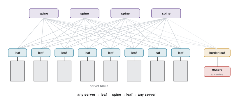
AI clusters add a separate back-end network that connects GPUs in different servers to each other with very high bandwidth and low latency, typically using InfiniBand or specialized Ethernet. A cluster of tens of thousands of GPUs may need hundreds of thousands of optical connections. Because cable lengths are limited (especially for copper links of a few metres) and every metre adds latency, the network design constrains how racks are arranged and how large a single hall can be.
Worked problem
Counting uplinks in a leaf-spine pod
A pod has 32 leaf switches and 8 spine switches. Each leaf connects to each spine with two 400 Gb/s links. How many cables run between the leaf and spine layers, and what is the total capacity between them?
Show solution
- Cables: \(32 \times 8 \times 2 = 512\).
- Capacity: \(512 \times 400 = 204{,}800\) Gb/s, about 205 Tb/s (each direction).
Answer: 512 fibre cables between the layers, each typically a duplex or multi-fibre connection. A large facility with many pods has tens of thousands of such links, which is why cable pathways, labelling and documentation matter as much as the switches themselves.
Structured cabling and spaces
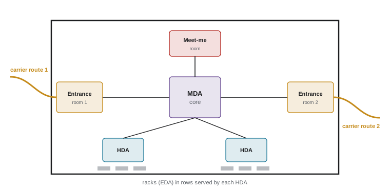
Cabling in a data centre is organized as structured cabling: permanent, tested links between defined spaces, with patch panels where connections are made and changed, rather than ad hoc cables run directly between devices. The ANSI/TIA-942 standard for data centre infrastructure defines a hierarchy of spaces:
- Entrance room (ER): where carriers' outside cables enter the building and terminate; often two, at opposite sides of the building, for diversity.
- Main distribution area (MDA): the core of the network, with core routers and switches and the main cross-connects.
- Horizontal distribution area (HDA): intermediate distribution serving groups of rows.
- Equipment distribution area (EDA): the racks themselves.
- Zone distribution area (ZDA): an optional consolidation point in the floor or overhead.
Colocation facilities also have a meet-me room (MMR), a secure room where customers' cages connect to carriers and to each other through cross-connects, which the operator installs and charges for. Cross-connect revenue is an important part of the colocation business.
Copper and fibre
Short connections inside a rack often use copper: direct-attach copper (DAC) cables carry 100 Gb/s to 800 Gb/s over a few metres with very low power and cost. Longer links use optical fibre with transceivers that convert electrical signals to light:
- Multimode fibre, with a larger core, is used for shorter runs (up to about 100 m at high speeds) with lower-cost transceivers.
- Single-mode fibre, with a very small core, carries signals for kilometres and is used between halls, buildings and cities; it is increasingly used throughout new data centres.
High-density fibre uses multi-fibre MPO connectors carrying 8, 12, 16 or 24 fibres in one connector. Every connection and splice loses some light, so designers calculate a loss budget to make sure the light reaching the receiver is strong enough (DCE-320).
Worked problem
Fibre count for a cluster
An AI cluster has 2,048 GPUs, each with one 400 Gb/s back-end link to a leaf switch using an 8-fibre transceiver connection. The leaf-to-spine layer has the same total number of links. How many fibres are needed?
Show solution
- GPU-to-leaf links: 2,048; leaf-to-spine links: 2,048; total 4,096 links.
- Fibres: \(4096 \times 8 = 32{,}768\).
Answer: About 33,000 fibres for a modest cluster, before the front-end and management networks. Clusters of 100,000 GPUs need millions of fibres, requiring large overhead trays, careful routing and many weeks of installation and testing.
Pathways and physical design
Cables need pathways: overhead ladder racks and basket trays, fibre raceway systems, underfloor trays in raised-floor rooms, and conduits between rooms and buildings. Designers must:
- Size trays for the expected cable count with room to grow (fill is usually limited to about 50% of tray depth to allow additions and airflow).
- Coordinate trays with busways, lighting, sprinklers, containment and liquid cooling pipes, all competing for the same overhead space.
- Keep the minimum bend radius of fibre and protect it from damage.
- Separate the A and B network paths physically, as with power.
- Provide fire-stopping where cables pass through rated walls (Lesson 9).
Worked problem
Tray fill
A fibre tray 300 mm wide and 100 mm deep may be filled to 50% of its cross-section. Each fibre trunk cable has a diameter of 12 mm. Roughly how many cables fit?
Show solution
- Usable area: \(0.5 \times 300 \times 100 = 15{,}000\) mm².
- Cable area: \(\pi \times 6^2 = 113\) mm²; allowing for gaps (multiply by about 1.27 for round cables): 144 mm² each.
- Cables: \(15000/144 = 104\).
Answer: About 100 trunk cables. Designers check fill against standards and manufacturer guidance and plan multiple tray levels in AI halls.
Connecting the building to the world
Outside the building, fibre cables run to carriers' networks and other data centres along routes that should be physically diverse: two or more cables entering at different points, following different streets or rights of way, so that a single backhoe or construction accident cannot cut all connections. Fibre cuts from excavation are one of the most common causes of network outages. Large campuses build their own duct banks and lease or build dark fibre (unlit fibre that the customer lights with its own equipment) to other sites. Long-distance capacity is multiplied with dense wavelength division multiplexing (DWDM), which carries dozens of wavelengths, each at hundreds of gigabits per second, on one fibre pair.
Connectivity is planned with the site from the beginning (Lesson 11): how many carriers are nearby, how long new fibre routes would take to permit and build, and whether diverse routes are available. A site with ample power but no fibre may take years to connect.
Keeping the network running
Network equipment has its own reliability design. Servers usually connect to two leaf switches, so a switch can fail or be upgraded without disconnecting them; every leaf connects to several spines; and routing protocols redirect traffic within milliseconds when a link or switch fails. Power for network equipment follows the same A and B feed principles as servers, and the core network rooms (MDA and entrance rooms) are often placed in the most protected part of the building with their own cooling.
Most network outages are caused not by hardware but by configuration changes, software bugs and fibre cuts. Network teams therefore use automation to apply changes consistently, test changes in staging environments, roll them out gradually, and keep detailed documentation of every cable and port. Physical labelling matters: a single mislabelled patch cord can take down a customer, and audits of cable records against reality are a routine part of operations.
Worked problem
Dual-homed servers
A rack's 40 servers each connect to two leaf switches with one 100 Gb/s link each. One leaf fails. What bandwidth does each server keep, and what share of the rack's total uplink capacity remains?
Show solution
- Each server keeps one of its two links: 100 Gb/s of 200 Gb/s.
- Rack capacity falls from \(40 \times 200 = 8000\) Gb/s to 4000 Gb/s, 50%.
Answer: Every server stays connected at half bandwidth. For most applications this is acceptable while the switch is replaced; designers size links so that critical traffic fits within the surviving capacity.
Common mistakes
MistakeIgnoring latency when choosing a site.
InsteadAllow about 5 µs per km of fibre each way plus equipment delay.
MistakeRunning both carrier entrances along the same route.
InsteadUse physically diverse routes and separate entrance rooms.
MistakePatching cables directly between devices across a hall.
InsteadUse structured cabling with patch panels and documentation.
MistakeSizing cable trays for day-one cables only.
InsteadLimit fill and plan for growth, especially for AI fabrics.
MistakeTreating network design as separate from the building.
InsteadCoordinate pathways, cable lengths and layout early.
Summary and key terms
- Bandwidth is measured in bits per second; links have grown to 400 Gb/s and 800 Gb/s.
- Light in fibre travels about 200 km per millisecond: roughly 5 µs/km one way.
- Latency and interconnection drive clustering in hubs, availability zones and edge sites.
- Leaf-spine fabrics connect every leaf to every spine; AI clusters add high-bandwidth back-end networks.
- TIA-942 defines entrance rooms, MDA, HDA and EDA; colocation adds meet-me rooms.
- Copper serves short links; multimode and single-mode fibre serve longer ones.
- Pathways must be sized, coordinated, diverse and fire-stopped.
- Diverse outside routes protect against fibre cuts.
- Bandwidth
- The data rate a link can carry, in bits per second.
- Latency
- The time for data to travel between two points.
- Round-trip time
- The time for a signal to go and return.
- Leaf-spine
- A network where every leaf switch connects to every spine switch.
- Structured cabling
- Permanent, standardized cabling between defined spaces and patch panels.
- Entrance room
- The space where outside carrier cables enter and terminate.
- Meet-me room
- A room where customers connect to carriers and to each other.
- Cross-connect
- A cable linking two parties' equipment in a data centre.
- Dark fibre
- Unlit fibre leased or owned and lit by the user.
- DWDM
- Dense wavelength division multiplexing: many wavelengths on one fibre.
Practice problems
Work each problem on paper first, then reveal the answer to check.
How many gigabytes per second does a 400 Gb/s link carry?
Show answer
50 GB/s.
One-way propagation delay over 80 km of fibre?
Show answer
400 µs.
Maximum fibre distance for a 1 ms round trip (propagation only)?
Show answer
100 km.
Why do cloud providers place availability zones tens of kilometres apart?
Show answer
Close enough for low latency, far enough apart to avoid shared disasters.
16 leaves and 4 spines with one link each. Leaf-spine cables?
Show answer
64.
What is the main distribution area?
Show answer
The core space with core switches, routers and main cross-connects.
What is a meet-me room?
Show answer
A secure room where customers connect to carriers and each other.
When is multimode fibre used?
Show answer
For shorter runs, up to about 100 m at high speeds.
1,024 links with 8 fibres each. Total fibres?
Show answer
8,192.
What is a common cause of network outages outside the building?
Show answer
Fibre cuts from excavation or construction.
Lesson quiz · 5 questions
Score 60% or more to complete this lesson.
Create a free account to save your progress, take quizzes and earn a certificate.