
DCE-200 · Lesson 6 of 12 · 34 min
Airflow management and liquid cooling
Lesson 5 explained how heat moves from servers to the outdoors and introduced hot and cold aisles, cooling units and liquid cooling. This lesson goes inside the white space in more detail. The first half deals with air: how much air the servers need, how it is delivered, how it goes wrong through bypass and recirculation, and how operators measure and fix it. The second half deals with liquid: how direct-to-chip systems are arranged, how coolant distribution units link the racks to the building, what temperatures and flows they use, and the practical issues of water quality, leaks and mixed air and liquid halls. Together they explain why a hall that looks adequate on paper can still have hot spots, and why AI has made liquid cooling routine.
Supplying the right amount of air
Every server draws a certain airflow through its fans, set by its power and temperature rise (Lesson 2). The cooling units must supply at least the total airflow of the servers, plus a margin, at a suitable temperature. Using \(\rho c_p \approx 1.2\) kJ/(m³·K) for air:
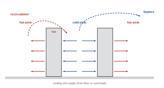
If the cooling units supply less air than the servers draw, the servers pull hot exhaust air around the ends and tops of the rows (recirculation), raising their inlet temperatures. If the units supply much more air than the servers draw, the excess bypasses the servers and returns to the units without picking up heat (bypass), wasting fan energy and lowering the return temperature, which reduces cooling unit capacity and efficiency.
Worked problem
Airflow for a row
A row of 20 racks draws 300 kW. The servers have an average temperature rise of 12 K. What airflow do they draw? If the cooling units supply 25% more than that, how much air bypasses?
Show solution
- Server airflow: \(300/(1.2 \times 12) = 20.8\) m³/s.
- Supplied: \(1.25 \times 20.8 = 26.0\) m³/s; bypass \(= 5.2\) m³/s.
Answer: About 21 m³/s (44,000 CFM) for the servers, with 5.2 m³/s bypassing. The bypass mixes with server exhaust, so the air returning to the cooling units is cooler than the 12 K rise suggests, and the units work less efficiently. Good containment lets operators reduce oversupply to a few percent.
Raised floors and slab floors
Older and some current data centres supply cold air through a raised floor: a plenum 450 mm to 1,200 mm deep beneath removable floor tiles, pressurized by the cooling units, with perforated tiles placed in front of racks. Each tile delivers a flow that depends on its open area and the plenum pressure; a typical 25% perforated tile delivers roughly 0.2 m³/s to 0.4 m³/s, enough for perhaps 3 to 6 kW of IT load, while high-flow grates deliver more. Cables and pipes under the floor obstruct airflow and cause uneven pressure, and tiles too close to cooling units may even draw air downward because of high velocity under the floor.
Many modern facilities use slab floors with air delivered from above or through fan walls on one side of the hall into contained cold aisles or flooded rooms. Slab floors carry heavy racks more easily, avoid underfloor obstructions and cost less; cables and busways run overhead. Raised floors remain useful where pipework for liquid cooling or legacy layouts favour them.
Worked problem
Tiles needed for a rack row
A cold aisle serves 16 racks at 8 kW each, with a 12 K server temperature rise. Perforated tiles each deliver 0.3 m³/s at the design plenum pressure. How many tiles are needed?
Show solution
- Load: \(16 \times 8 = 128\) kW. Airflow: \(128/(1.2 \times 12) = 8.9\) m³/s.
- Tiles: \(8.9/0.3 = 29.6\), so 30 tiles (plus a margin).
Answer: About 30 tiles, nearly two per rack. A cold aisle with only one tile per rack would starve the servers. At 20 kW per rack the same aisle would need about 74 tiles, more than fit, which is why higher densities move to contained aisles with grates, overhead supply or liquid cooling.
Measuring air management
Operators measure how well air is managed using sensors at rack inlets and outlets and at cooling units:
- Rack inlet temperature: the temperature that matters to the equipment, compared with the ASHRAE recommended range of 18 °C to 27 °C (Lesson 5).
- Temperature rise across the cooling units versus across the servers: if units see a much smaller rise than the servers produce, air is bypassing.
- Return Temperature Index (RTI): the ratio of the cooling units' temperature rise to the IT equipment's rise; 100% is balanced, below 100% indicates bypass, above 100% indicates recirculation.
- Rack Cooling Index (RCI): how many inlet temperatures fall outside the recommended range.
Computational fluid dynamics (CFD) models simulate airflow in a hall during design and before major changes, showing where hot spots will appear and testing remedies. Thermal imaging and wireless temperature sensors at the top, middle and bottom of rack fronts give operators continuous feedback.
Worked problem
Return Temperature Index
Cooling units supply 20 °C air and receive return air at 28 °C. The servers raise air temperature by an average of 13 K. What is the RTI, and what does it suggest?
Show solution
- Cooling unit rise: \(28 - 20 = 8\) K.
- RTI: \(8/13 = 62\%\).
Answer: An RTI of 62% means a lot of cold air is bypassing the servers and diluting the return. Remedies include sealing openings with blanking panels and brush grommets, adding containment, removing unnecessary perforated tiles and slowing the cooling unit fans. Fan power falls with the cube of speed, so reducing airflow by 20% saves about half the fan energy.
Fixing hot spots: practical measures
Most air management problems have simple, inexpensive fixes:
- Install blanking panels in every empty rack unit and seal gaps between racks and at the bottom of racks.
- Seal cable openings in raised floors with brush grommets.
- Contain hot or cold aisles with doors and roofs; seal containment carefully, including above doors and around cable trays.
- Place perforated tiles only in cold aisles, matched to the load.
- Avoid placing high-density racks at the ends of rows, where recirculation is worst.
- Manage cables so they do not block server exhaust.
- Control cooling unit fans from rack inlet temperatures or containment pressure rather than return temperature.
With good air management, supply temperatures can rise toward the upper end of the recommended range, which extends economizer hours (Lesson 5) and reduces chiller energy.
Why liquid cooling
Water carries about 3,500 times more heat per unit volume than air for the same temperature rise. Air cooling becomes impractical above roughly 30 kW to 50 kW per rack because the airflow, fan noise and heat sink size grow too large, and because the processor chips themselves now dissipate 700 W to over 1,000 W each in small areas. Liquid cooling moves heat at the chip, at higher temperatures, with less pumping energy, and allows much denser racks.
Direct-to-chip cooling systems
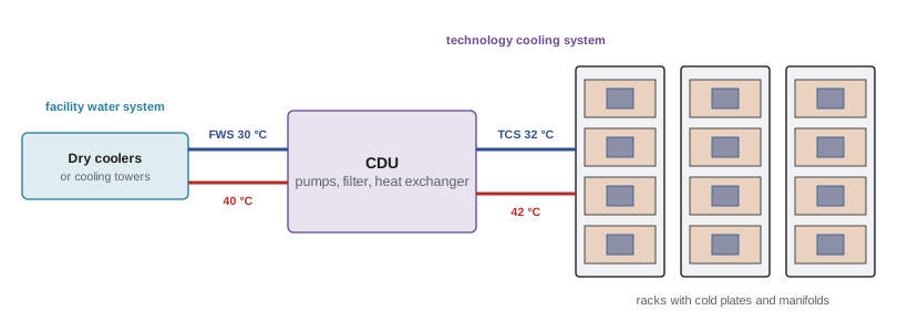
In direct-to-chip (cold plate) cooling, the liquid loop is divided into two circuits separated by a heat exchanger:
- The technology cooling system (TCS) is the secondary loop running through the racks and cold plates. It uses treated water or a water-propylene glycol mixture, clean and filtered because the cold plates have fine channels, at controlled temperature and pressure.
- The facility water system (FWS) is the building's primary loop, connected to chillers, cooling towers or dry coolers.
A coolant distribution unit (CDU) contains the heat exchanger between the two loops, pumps, filters, expansion tanks and controls. CDUs may sit in each rack (rack-mounted), at the end of a row (in-row) or in a separate gallery serving many racks. Manifolds in each rack distribute coolant to each server through drip-free quick-disconnect couplings.
Cold plates usually capture 70% to 90% of a server's heat; the rest, from memory, power supplies, network cards and drives, still goes to air. A liquid-cooled hall therefore still needs air cooling, at a smaller scale, often through rear-door heat exchangers or fan walls.
Worked problem
Splitting the heat
A hall has 64 liquid-cooled AI racks of 130 kW each. Cold plates capture 80% of the heat. Size the liquid flow for a 10 K rise and find the remaining air-side heat.
Show solution
- Total heat: \(64 \times 130 = 8320\) kW. Liquid: \(0.8 \times 8320 = 6656\) kW; air: 1664 kW.
- Liquid flow: \(6656/(4.18 \times 10) = 159\) kg/s, about 159 L/s (2,500 US gpm).
Answer: About 159 L/s of coolant for 6.7 MW, plus 1.7 MW of air-side cooling, the equivalent of a conventional data hall. Designers must size both systems and keep the air system working when the liquid system is maintained.
Temperatures and warm-water cooling
Cold plates can operate with surprisingly warm coolant. ASHRAE defines liquid cooling classes by facility water supply temperature, from W17 (up to 17 °C) to W45 (up to 45 °C) and above. Many AI systems accept TCS supply temperatures of 30 °C to 45 °C. Warm water means that in most climates heat can be rejected with dry coolers or cooling towers without chillers for most or all of the year, cutting energy use; it also produces return water warm enough to be useful for heat reuse (Lesson 10). The approach temperature, the difference between the facility water and TCS temperatures across the CDU heat exchanger, is typically 2 K to 5 K.
Worked problem
Free cooling hours
A facility needs TCS supply at 35 °C. The CDU approach is 3 K and dry coolers need the facility water to be 6 K above the outdoor dry-bulb temperature. Above what outdoor temperature are chillers or adiabatic assist needed?
Show solution
- Facility water supply needed: \(35 - 3 = 32\) °C.
- Maximum outdoor temperature for dry coolers: \(32 - 6 = 26\) °C.
Answer: Above about 26 °C outdoors. In a cool climate this may be only a few hundred hours a year, met by evaporative assist rather than chillers. Raising the TCS supply to 40 °C would allow dry cooling up to 31 °C.
Water quality, leaks and reliability
Liquid near electronics raises understandable concern, and good practice addresses it:
- Water quality: the TCS is filled with treated water or glycol mixtures with corrosion inhibitors and biocides, filtered to protect fine cold plate channels (often to 50 µm or finer), and tested regularly. Wetted materials must be compatible to avoid galvanic corrosion.
- Leak prevention and detection: drip-free quick disconnects, pressure testing during commissioning, leak detection cables under racks and manifolds, and controls that isolate a leaking rack automatically.
- Negative-pressure systems: some designs keep the TCS below atmospheric pressure so that a leak draws air in rather than pushing liquid out.
- Redundancy: CDUs and pumps are installed N+1 or better, and the cooling path is as important as the power path; an AI rack without coolant overheats within seconds to minutes.
- Thermal ride-through: when power fails, pumps must keep running on UPS power, or the chips overheat before generators start.
Immersion cooling
Immersion cooling submerges servers in a dielectric fluid. In single-phase immersion, the fluid (usually a hydrocarbon or synthetic oil) stays liquid and is pumped through a heat exchanger. In two-phase immersion, the fluid boils at the hot components and condenses on a coil above, carrying heat very effectively; however, many two-phase fluids are fluorinated chemicals (PFAS) facing regulatory restrictions, which has slowed adoption. Immersion removes nearly all heat to liquid and eliminates server fans, but tanks change floor layouts, the fluid adds weight, and servicing requires lifting equipment out of the fluid. It is used in some cryptocurrency, edge and high-performance installations, while direct-to-chip has become the mainstream approach for AI.
Planning for mixed halls
Most new halls must accommodate both air-cooled and liquid-cooled equipment, often in unknown proportions over their life. Common strategies include installing facility water piping and CDU connection points throughout the hall from the start, even where initial racks are air-cooled; designing air systems that can be reduced as liquid takes over; reserving floor space and structural capacity for CDUs; and choosing cooling plants able to supply both cold water for air cooling and warm water for liquid cooling. Retrofitting liquid cooling into an occupied hall is possible but disruptive, so these early decisions are among the most important in modern data centre design.
Common mistakes
MistakeOversupplying air to fix hot spots.
InsteadFind and seal bypass and recirculation paths; match supply to demand.
MistakeLeaving empty rack spaces open.
InsteadInstall blanking panels to stop recirculation.
MistakeAssuming liquid-cooled halls need no air cooling.
InsteadCold plates capture 70% to 90%; size air cooling for the rest.
MistakeRunning cold plate loops on untreated water.
InsteadUse treated, filtered coolant and monitor quality.
MistakePutting CDU pumps on non-UPS power.
InsteadKeep coolant flowing through power transfers.
Summary and key terms
- Cooling units must supply the airflow servers draw; too little causes recirculation, too much causes bypass.
- Raised-floor tiles deliver limited airflow; high densities need containment, overhead supply or liquid.
- RTI, RCI and inlet temperatures measure air management; CFD predicts it.
- Blanking panels, sealing and containment are cheap, effective fixes.
- Water carries far more heat than air; chips above 700 W need liquid cooling.
- Direct-to-chip systems use a TCS loop, CDUs and a facility water loop; 10% to 30% of heat still goes to air.
- Warm-water cooling enables chiller-free operation and heat reuse.
- Coolant quality, leak detection, redundancy and ride-through make liquid cooling reliable.
- Bypass airflow
- Cooling air that returns to cooling units without passing through IT equipment.
- Recirculation
- Hot exhaust air drawn back into server inlets.
- Perforated tile
- A raised-floor tile with openings that delivers cool air.
- Return Temperature Index
- Cooling unit temperature rise divided by IT temperature rise.
- CFD
- Computational fluid dynamics; simulation of airflow and heat.
- Technology cooling system
- The secondary liquid loop serving racks and cold plates.
- Facility water system
- The building's primary cooling water loop.
- Coolant distribution unit
- Equipment with pumps and a heat exchanger linking TCS and FWS.
- Approach temperature
- The temperature difference across a heat exchanger between the two fluids.
- Immersion cooling
- Cooling by submerging electronics in dielectric fluid.
Practice problems
Work each problem on paper first, then reveal the answer to check.
Airflow for 200 kW at a 15 K rise?
Show answer
200/(1.2 × 15) = 11.1 m³/s.
What is the difference between bypass and recirculation?
Show answer
Bypass: cold air skips servers; recirculation: hot air re-enters server inlets.
10 racks at 6 kW, 12 K rise, tiles of 0.25 m³/s. Tiles needed?
Show answer
60/(1.2 × 12) = 4.17 m³/s; 17 tiles.
Supply 22 °C, return 32 °C, IT rise 12 K. RTI?
Show answer
83%, indicating some bypass.
Reducing fan speed by 30% changes fan power by about?
Show answer
0.7³ = 0.34; about 66% saving.
Name three cheap air management fixes.
Show answer
Blanking panels, brush grommets, containment, correct tile placement.
Water flow to remove 500 kW with an 8 K rise?
Show answer
500/(4.18 × 8) = 15 kg/s ≈ 15 L/s.
A 100 kW rack with 85% cold plate capture. Air-side heat?
Show answer
15 kW.
TCS supply 40 °C, approach 4 K, dry cooler 7 K. Maximum outdoor temperature for dry cooling?
Show answer
29 °C.
Why must CDU pumps be on UPS power?
Show answer
High-density chips overheat in seconds to minutes without coolant flow.
Lesson quiz · 5 questions
Score 60% or more to complete this lesson.
Create a free account to save your progress, take quizzes and earn a certificate.