
CSCO-111 · Lesson 2 of 12 · 24 min
The OSI and TCP/IP models
▶ Video coming soon A video version of this lesson is on the way.
The sticky note on Jordan's monitor says 'which layer?', but in the first week Jordan admits to Dev that the layers themselves are still a blur. Dev pulls a chair over, takes a marker and draws seven stacked boxes on the whiteboard beside the service desk. He says that every network technician in the world uses this drawing as a shared language. When a colleague says a problem is 'a layer 1 issue', everyone knows to check cables, connectors and power. When a provider says 'layer 3 is fine', everyone knows routing and IP addressing have been checked. The models are not rules that networks obey; they are maps that help people talk about networks and find faults.
This lesson covers the two models the CCST Networking exam uses: the seven-layer OSI reference model and the four-layer TCP/IP model. It explains what each layer does, which protocols and devices belong where, how data is wrapped and unwrapped as it moves through the layers, and how technicians use the layers to troubleshoot.
Why networks are described in layers
Sending a web page from a server in another country to a phone on a café's Wi-Fi involves dozens of separate jobs. The page has to be formatted, the connection has to be reliable, the data has to be addressed to the right device, it has to find a path across many networks, it has to be turned into electrical signals, light or radio waves, and it has to be checked for errors at every step. Layering divides these jobs so that each layer only has to do its own work and trust the layers above and below it to do theirs.
Layering has practical benefits. A web browser does not care whether the phone is on Wi-Fi or a cellular network, because the lower layers hide that detail. A cable manufacturer can make better copper or fibre without changing the applications that run over it. A technician can test one layer at a time: if a laptop has a valid IP address and can reach its gateway, the cable and the switch are almost certainly fine, and the search can move up. Layering also lets different vendors' equipment work together, because each layer's job is defined by open standards.
The OSI reference model
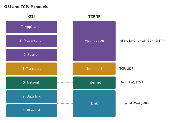
The Open Systems Interconnection model was published by the International Organization for Standardization in the 1980s. It divides communication into seven layers, numbered from the bottom. Layer 1, the physical layer, carries raw bits as signals over a medium: voltages on copper, pulses of light in fibre, or radio waves. Layer 2, the data link layer, moves frames between devices on the same local network, using hardware addresses such as Ethernet MAC addresses, and detects errors in each frame. Layer 3, the network layer, moves packets between networks, using logical addresses such as IP addresses, and chooses paths through routers. Layer 4, the transport layer, delivers data between applications on two hosts, using port numbers, and can provide reliability, ordering and flow control.
The upper three layers deal with the application's data. Layer 5, the session layer, sets up, manages and ends conversations between applications. Layer 6, the presentation layer, handles formatting, character encoding, compression and encryption, so that data sent by one system can be understood by another. Layer 7, the application layer, is where network services meet the programs people use: web browsing, email, file transfer and name lookups. In practice, many modern protocols combine the work of layers 5, 6 and 7, which is one reason the simpler TCP/IP model is used to describe real networks.
Technicians remember the layers with a phrase. From layer 1 upward, 'Please Do Not Throw Sausage Pizza Away' gives physical, data link, network, transport, session, presentation and application. From layer 7 downward, 'All People Seem To Need Data Processing' works the other way. Pick one and practise it until you can write the seven layers in order without thinking.
| Layer | Name | Job | Data unit | Examples |
|---|---|---|---|---|
| 7 | Application | Network services for programs | Data | HTTP, DNS, SMTP, FTP |
| 6 | Presentation | Format, encode, compress, encrypt | Data | Character sets, TLS encryption, JPEG |
| 5 | Session | Open, manage and close conversations | Data | Session setup in remote desktop or SQL connections |
| 4 | Transport | Host-to-host delivery, ports, reliability | Segment (TCP) or datagram (UDP) | TCP, UDP |
| 3 | Network | Logical addressing and routing between networks | Packet | IPv4, IPv6, ICMP |
| 2 | Data link | Framing and local delivery by hardware address | Frame | Ethernet, Wi-Fi (802.11), ARP |
| 1 | Physical | Bits as signals on a medium | Bits | Cables, connectors, radio, hubs |
The TCP/IP model
The protocols that run the internet were developed in the 1970s and 1980s alongside, and partly before, the OSI model. They are described by a simpler model, usually called the TCP/IP model or internet model. In its common four-layer form it has a link layer at the bottom, also called the network access layer, which covers what OSI calls the physical and data link layers. Above it is the internet layer, matching OSI layer 3, where IP lives. Above that is the transport layer, where TCP and UDP live. At the top is the application layer, which covers the work of OSI layers 5, 6 and 7.
Some textbooks and Cisco materials show a five-layer version that splits the link layer into separate physical and data link layers. Both versions describe the same protocols; the five-layer version simply lines up more neatly with OSI layers 1 to 4. On the exam, read each question carefully to see which model it is asking about. A question that asks which TCP/IP layer IP belongs to wants 'internet', while the same question about OSI wants 'network' or 'layer 3'.
Where devices sit
Devices are often described by the highest layer they work at. A hub, now mostly obsolete, is a layer 1 device: it repeats every signal it receives out of every other port, without reading any addresses. A switch is a layer 2 device: it reads the destination MAC address in each frame and forwards the frame only out of the port where that address lives. A router is a layer 3 device: it reads the destination IP address in each packet and forwards it towards the right network. Many modern switches can also route, and these are called layer 3 switches or multilayer switches.
Other devices work higher up. A traditional firewall filters traffic using layer 3 and layer 4 information, such as addresses and port numbers. A next-generation firewall also inspects application data at layer 7. A wireless access point bridges between the radio network and the wired Ethernet network, working mainly at layers 1 and 2. A computer or phone, which runs applications, works at every layer. Lesson 9 looks at these devices in more detail.
Encapsulation: wrapping data on the way down
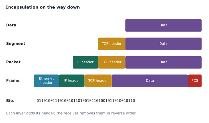
When an application sends data, each layer adds its own information before passing the data down. This is called encapsulation. Suppose Jordan's browser requests a web page. The application layer creates an HTTP request. The transport layer adds a TCP header with the source and destination port numbers, a sequence number and other control information, making a segment. The network layer adds an IP header with the source and destination IP addresses, making a packet. The data link layer adds an Ethernet header with the source and destination MAC addresses, and a trailer with an error check, making a frame. The physical layer turns the frame into signals on the cable.
On the receiving side, each layer reads and removes its own header and passes the rest upward. This is called de-encapsulation. The receiving network card checks the frame for errors and confirms that it is addressed to this device, the IP layer checks that the packet is for this host, the TCP layer puts the segments back in order and passes the data to the right application by port number, and the web server reads the HTTP request. Routers along the way de-encapsulate only as far as layer 3: they remove the Ethernet frame, read the IP header, choose the next hop, and then wrap the packet in a new frame for the next link.
The names for the data at each stage are called protocol data units, or PDUs. The exam expects you to know them: bits at layer 1, frames at layer 2, packets at layer 3, and segments at layer 4 for TCP. UDP's unit is usually called a datagram. Above layer 4, the PDU is simply called data.
Using the layers to troubleshoot
The layers give technicians an order in which to test. The bottom-up approach starts at layer 1 and works upward: Is the device powered and the link light on? Does the network adapter show a connection? Does the device have a valid IP address and gateway? Can it ping the gateway? Can it resolve names? Can the application connect? Each answer either finds the fault or rules out a layer. Bottom-up is thorough and is a good default for new technicians, because physical problems are common and quick to check.
Two other approaches are useful. Top-down starts at the application and works down, which suits problems where only one program fails. Divide and conquer starts in the middle, usually with a ping test at layer 3: if a ping to a remote server works, layers 1 to 3 are fine and the problem is higher up; if it fails, the problem is at layer 3 or below. Experienced technicians often begin with divide and conquer because it halves the search immediately. CSCO-112 covers troubleshooting methods in detail; for now, the goal is to connect each symptom with the layer it points to.
| Symptom | Likely layer | First checks |
|---|---|---|
| No link light on the switch port | 1 | Cable seated, cable damage, port enabled, device powered |
| Link up but no address, or a 169.254 address | 2 or 3 | DHCP reachability, switch port VLAN, adapter settings |
| Can ping by IP address but not by name | 7 (DNS) | DNS server settings, name resolution test |
| Local resources work, remote sites do not | 3 | Default gateway, routing, provider link |
| One application fails, others work | 4 to 7 | Port blocked by firewall, service down, application settings |
Worked problem
Placing protocols on the models
A technician's notes mention Ethernet, IPv4, TCP, DNS and the physical cable. Place each on the OSI model and on the four-layer TCP/IP model.
Show solution
- The cable carries signals, so it is OSI layer 1, physical, and part of the TCP/IP link layer.
- Ethernet frames carry MAC addresses, so Ethernet is OSI layer 2, data link, and also part of the TCP/IP link layer.
- IPv4 addresses and routes packets, so it is OSI layer 3, network, and the TCP/IP internet layer.
- TCP provides ports and reliable delivery, so it is OSI layer 4 and the TCP/IP transport layer.
- DNS is a service used by applications, so it is OSI layer 7 and the TCP/IP application layer.
Answer: Cable and Ethernet: OSI 1 and 2, TCP/IP link. IPv4: OSI 3, internet. TCP: OSI 4, transport. DNS: OSI 7, application.
Worked problem
Following a fault with the layers
At Riverside Family Law, a paralegal says the document-management system is 'down'. Her laptop shows a Wi-Fi connection with a valid address, she can open the firm's intranet page, and other staff can use the document system normally. Which layers can be ruled out, and where should the technician look?
Show solution
- The laptop is connected and has a valid address, so layers 1 to 3 on her side are working.
- She can open the intranet page, so DNS and general web access work.
- Other staff can use the system, so the server and the network path to it are working.
- The fault is probably at the application level on her laptop: the document-management client, her account, or a saved setting.
Answer: Layers 1 to 3 and the server are ruled out. Start with the application on her laptop and her account.
Jordan copies the whiteboard drawing into the notebook and adds a column for 'what I would check'. Dev says the habit will pay off for years. In the next lesson they look closely at layer 2, where Ethernet frames and MAC addresses do the local work of every wired network.
Common mistakes
MistakeSaying a switch works at layer 3 because it has an IP address for management.
InsteadA basic switch forwards frames by MAC address at layer 2; its management address does not change how it forwards traffic.
MistakeCalling a layer 3 PDU a frame.
InsteadFrames are layer 2; packets are layer 3; segments are layer 4.
MistakeAssuming TCP/IP has seven layers.
InsteadThe common TCP/IP model has four layers; some books show five by splitting the link layer.
MistakePlacing DNS at the transport layer because it uses UDP.
InsteadDNS is an application-layer service that uses UDP or TCP for transport.
MistakeStarting every troubleshooting job at the application.
InsteadBottom-up or divide and conquer usually finds faults faster; choose the method to fit the symptom.
Summary and key terms
- Layered models divide network communication into separate jobs and give technicians a shared language.
- The OSI model has seven layers: physical, data link, network, transport, session, presentation and application.
- The four-layer TCP/IP model has link, internet, transport and application layers.
- Hubs work at layer 1, switches at layer 2, routers at layer 3; firewalls filter at layers 3 and 4 and sometimes 7.
- Encapsulation adds headers on the way down; de-encapsulation removes them on the way up.
- PDUs are bits, frames, packets and segments (or datagrams) at layers 1 to 4.
- Bottom-up, top-down and divide and conquer use the layers to narrow down faults.
- OSI model
- The seven-layer reference model for network communication.
- TCP/IP model
- The four-layer model that describes internet protocols.
- Encapsulation
- Adding a layer's header, and sometimes a trailer, to data passed down from the layer above.
- PDU
- Protocol data unit: the name for data at a given layer, such as frame or packet.
- Frame
- The layer 2 unit, carrying MAC addresses and an error check.
- Packet
- The layer 3 unit, carrying IP addresses.
- Segment
- The TCP unit at layer 4, carrying port numbers and sequence information.
- Divide and conquer
- Troubleshooting that starts at a middle layer and moves up or down depending on the result.
Practice problems
Work each problem on paper first, then reveal the answer to check.
List the OSI layers from 1 to 7.
Show answer
Physical, data link, network, transport, session, presentation, application.
Which TCP/IP layer contains IP?
Show answer
The internet layer.
What is the PDU at OSI layer 2?
Show answer
A frame.
At what layer does a switch forward traffic?
Show answer
Layer 2, using MAC addresses.
What does a router do with the Ethernet header of a packet it forwards?
Show answer
It removes it, reads the IP header, and builds a new frame for the next link.
A user can ping a server by IP address but not by name. Which service should you check?
Show answer
DNS, an application-layer service.
Lesson quiz · 5 questions
Score 60% or more to complete this lesson.
Create a free account to save your progress, take quizzes and earn a certificate.