
CIV-331 · Lesson 9 of 12 · 21 min
Bolted connections
Connections are where steel structures most often go wrong, and where much of their cost lies. A member that is a little oversized costs a few kilograms of steel; a connection that is awkward to make costs hours of shop and field labour. Most field connections in steel buildings are bolted, because bolting is fast, needs little skill on site and works in any weather. This lesson covers high-strength bolts and how they are installed, the limit states of bolted joints, the double-angle connections of the mezzanine beams, and a bolt group loaded eccentrically by the monorail bracket.
High-strength bolts
Structural bolts in Canada are specified to ASTM F3125, which covers grade A325 (tensile strength 825 MPa for the common sizes) and grade A490 (1035 MPa), in metric and inch sizes. M20 and M22 bolts, or their inch equivalents 3/4 and 7/8 in., are the workhorses of building construction. Lower-strength ASTM A307 bolts are used only for minor connections. Each bolt has a heavy hex head and nut and usually a hardened washer, and twist-off-type tension-control versions are common.
Bolts can be installed in three ways, which give three kinds of joint:
- Snug-tight: the plies are drawn into firm contact by a few impacts of an impact wrench or the full effort of a worker with a spud wrench. Most shear connections in buildings are snug-tight bearing-type joints.
- Pretensioned: each bolt is tightened to a minimum tension of about 70 per cent of its tensile strength, by turn-of-nut, a calibrated wrench, twist-off bolts or direct tension indicators. Pretension is required for joints with load reversal, fatigue, or bolts in tension, and in some seismic systems.
- Slip-critical: pretensioned joints in which the clamping force, through friction on prepared faying surfaces, is designed to prevent slip. They are used where slip would be harmful: joints with oversized or slotted holes in the direction of load, crane runways, fatigue loading and joints with load reversal.
In a bearing-type joint, the plies slip into bearing against the bolts, and the bolts carry the load in shear. The pretension in a slip-critical joint does not change the ultimate strength much; it changes behaviour at service loads.
Hole sizes, spacing and edge distance
Standard holes are 2 mm larger than the bolt for M24 and smaller. Oversized and slotted holes give erection tolerance but need pretensioned or slip-critical bolts in some cases. S16 requires a minimum spacing of 2.7 bolt diameters (3d is normal practice), and minimum edge distances that depend on the bolt size and whether the edge is sheared or rolled; for an M20 bolt about 34 mm to a sheared edge and 26 mm to a rolled or gas-cut edge. Maximum spacings and edge distances keep plies in contact and prevent corrosion between them.
Limit states of a bearing-type joint
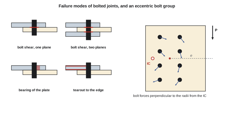
Bolt shear. The shear resistance of a bolt depends on its tensile strength and on whether threads lie in the shear plane, which reduces the area:
where \(n\) is the number of bolts, \(m\) the number of shear planes, and \(A_b\) the area of the bolt shank. Designers usually assume threads are intercepted unless the grip and bolt length guarantee otherwise.
Bearing and tearout. The plate behind each bolt may deform excessively in bearing, or the bolt may tear out to the edge. S16 gives \(B_r = 3\phi_{br}\,t\,d\,n\,F_u\) with \(\phi_{br} = 0.80\) for bearing, and checks tearout to an edge as part of block shear.
Block shear and net fracture of the connected parts, from lesson 3, complete the list. For coped beams, block shear of the web is often the critical check.
The mezzanine beam connection
Each mezzanine beam is connected to the girder web with a pair of clip angles, shop-bolted to the beam web and field-bolted to the girder. Three M20 A325 bolts pass through the angles and the beam web in double shear, at a 75 mm pitch with the top bolt 40 mm below the cope, and three bolts on each angle connect it to the girder. The top flange of the beam is coped 40 mm deep so that it clears the girder flange.
Worked problem
Double-angle connection of a mezzanine beam
Check the beam side of the connection for \(V_f = 152\) kN: bolt shear, bearing on the 8.0 mm beam web (\(F_u = 450\) MPa), and block shear of the coped web with a 40 mm end distance.
Show solution
- Bolt shear, double shear, threads intercepted:
- \[V_r = 0.60(0.80)(3)(2)(314)(825)(0.70) = 522\ \text{kN}\]
- Bearing on the beam web:
- \[B_r = 3(0.80)(8.0)(20)(3)(450) = 518\ \text{kN}\]
- Block shear of the web with \(U_t = 0.6\): the shear plane runs from the bottom bolt up to the cope, \(40 + 2(75) = 190\) mm, and the tension plane from the bolt line to the beam end:
- \[A_{gv} = 190(8.0) = 1520\ \text{mm}^2 \qquad A_n = (40 - 12)(8.0) = 224\ \text{mm}^2\]
- \[T_r = 0.75\Big[0.6(224)(450) + 0.6(1520)\,\frac{345 + 450}{2}\Big] = 317\ \text{kN}\]
Answer: Block shear governs at 317 kN, about twice the reaction. The connection is adequate, and the same detail can be used for every mezzanine beam.
Three more checks complete the connection: the bolts and angles on the girder side, the shear yielding and rupture of the angles themselves, and the girder web bearing. Standard tables of double-angle connections, published by the CISC and AISC, give the capacity of common configurations directly, and fabricators like them because they repeat.
Eccentrically loaded bolt groups
When the load on a bolt group does not pass through its centroid, the group must resist a moment as well as a shear. The monorail beam in lesson 12 hangs from brackets bolted to the flanges of the wall columns, with the load some distance from the bolts. Each bracket has two vertical lines of four bolts.
The elastic method treats the plate as rigid and the bolts as elastic springs. The direct shear \(P/n\) is shared equally, and the moment \(M = Pe\) produces bolt forces proportional to the distance \(r\) from the centroid:
The bolt farthest from the centroid on the side of the load has the largest resultant. The method is simple and conservative, because it ignores the ductility of the bolts.
The instantaneous centre of rotation (IC) method is more realistic. Under an eccentric load, the plate rotates about a point, the instantaneous centre, and each bolt deforms in proportion to its distance from that point. The force in each bolt follows a load-deformation curve measured in tests, \(R = R_{ult}(1 - e^{-10\Delta})^{0.55}\), with \(\Delta\) in inches and a maximum of 0.34 in. (8.6 mm) at the most distant bolt. The location of the centre is found by trial so that the bolt forces are in equilibrium with the load. The result is a coefficient \(C\), the number of bolts that the group is effectively worth, which handbook tables list for standard patterns.
Worked problem
The monorail bracket
A bracket is bolted to a column flange with two lines of four M20 A325 bolts in single shear, gauge 140 mm and pitch 75 mm, and carries a vertical load at an eccentricity of 300 mm from the centroid of the group. Find the largest load by the elastic method and by the IC method.
Show solution
- Polar moment of the bolt group about its centroid:
- \[\sum r^2 = 8(70)^2 + 4(37.5)^2 + 4(112.5)^2 = 39\,200 + 5625 + 50\,625 = 95\,450\ \text{mm}^2\]
- For a load of 60 kN, the corner bolt nearest the load has
- \[R_x = \frac{60(300)(112.5)}{95\,450} = 21.2\ \text{kN} \qquad R_y = \frac{60}{8} + \frac{60(300)(70)}{95\,450} = 7.5 + 13.2 = 20.7\ \text{kN} \qquad R = 29.6\ \text{kN}\]
- Single-shear resistance of one bolt: \(0.60(0.80)(314)(825)(0.70) = 87.0\) kN. Elastic method: \(P = 60(87.0/29.6) = 176\) kN.
- IC method (Sofia's program): \(C = 2.41\), so \(P = 2.41(87.0) = 209\) kN.
Answer: The IC method gives 19 per cent more capacity than the elastic method. Both are far above the factored monorail reaction found in lesson 12.
Sofia's program performs both checks of this lesson. The IC routine searches along the horizontal line through the centroid for the centre that balances the forces.
import math
# Double-angle shear connection, W460x60 beam to girder: three M20 A325 bolts, CSA S16 13.11 and 13.12
phib, phibr, phiu = 0.80, 0.80, 0.75
Fub, Ab, d = 825.0, 314.0, 20.0
Vf = 151.5
Vr_bolt = 0.60 * phib * 2 * Ab * Fub * 0.70 / 1e3        # double shear, threads intercepted
print(f"Bolt shear: {Vr_bolt:.1f} kN per bolt (double shear), 3 bolts = {3*Vr_bolt:.0f} kN")
w, Fu, Fy = 8.0, 450.0, 345.0
Br = 3 * phibr * 3 * w * d * Fu / 1e3
print(f"Bearing on the beam web: Br = {Br:.0f} kN")
# Block shear in the coped web: 40 mm from top bolt to cope, 75 mm pitch, 40 mm from bolt line to beam end
ha = 24
Agv = (40 + 2 * 75) * w
An = (40 - ha / 2) * w
Tr_block = phiu * (0.6 * An * Fu + 0.6 * Agv * (Fy + Fu) / 2) / 1e3
print(f"Block shear in the coped web: Tr = {Tr_block:.0f} kN (Ut = 0.6)")
print(f"Governing resistance = {min(3*Vr_bolt, Br, Tr_block):.0f} kN against Vf = {Vf} kN")

# Eccentric bolt group: monorail bracket, two lines of four M20 bolts, gauge 140, pitch 75, e = 300 mm
P, e = 60.0, 300.0
pts = [(x, y) for x in (-70, 70) for y in (-112.5, -37.5, 37.5, 112.5)]
J = sum(x * x + y * y for x, y in pts)
M = P * e
worst = 0
for x, y in pts:
    rx = -M * y / J
    ry = -P / len(pts) - M * x / J
    worst = max(worst, math.hypot(rx, ry))
print(f"Elastic method: largest bolt force = {worst:.1f} kN under P = {P:.0f} kN")
Vr1 = 0.60 * phib * Ab * Fub * 0.70 / 1e3
print(f"Single-shear resistance per bolt = {Vr1:.1f} kN -> elastic method allows P = {P*Vr1/worst:.1f} kN")

# Instantaneous centre of rotation (load-deformation curve R = Rult(1 - exp(-10 D))^0.55, D in mm/25.4)
def ic_capacity():
    best = None
    for i in range(1, 4000):
        r0 = i * 0.1                                   # ICR at distance r0 left of the centroid
        rs = [math.hypot(x + r0, y) for x, y in pts]
        rmax = max(rs)
        Rs = [(1 - math.exp(-10 * 0.34 * r / rmax))**0.55 for r in rs]
        Ry = sum(R * (x + r0) / r for R, r, (x, y) in zip(Rs, rs, pts))
        Mic = sum(R * r for R, r in zip(Rs, rs))
        Pn = Mic / (e + r0)                            # moment about the ICR
        if best is None or abs(Pn - Ry) < best[0]:
            best = (abs(Pn - Ry), Pn, r0)
    return best[1], best[2]
C, r0 = ic_capacity()
print(f"IC method: coefficient C = {C:.2f} bolts (ICR {r0:.0f} mm from centroid) -> P = {C*Vr1:.1f} kN")Bolt shear: 174.1 kN per bolt (double shear), 3 bolts = 522 kN Bearing on the beam web: Br = 518 kN Block shear in the coped web: Tr = 317 kN (Ut = 0.6) Governing resistance = 317 kN against Vf = 151.5 kN Elastic method: largest bolt force = 29.6 kN under P = 60 kN Single-shear resistance per bolt = 87.0 kN -> elastic method allows P = 176.2 kN IC method: coefficient C = 2.41 bolts (ICR 53 mm from centroid) -> P = 209.4 kN
Bolts in tension and combined loading
Bolts in tension, such as those in a hanger or a moment end plate, have a resistance \(T_r = 0.75\phi_bA_bF_u\). If the connected plates are flexible, they bend and pry against each other near their edges, adding a prying force to the bolt tension; thick plates or stiffeners reduce it. Bolts in combined shear and tension satisfy an elliptical interaction, \((V_f/V_r)^2 + (T_f/T_r)^2 \le 1.0\).
Slip-critical joints
The slip resistance of a joint depends on the clamping force of the pretensioned bolts, the number of faying surfaces and their slip coefficient, about 0.30 for clean mill scale and 0.50 for blast-cleaned surfaces with suitable coatings. S16 checks slip at specified loads, because in most buildings slip is a serviceability matter, and the joint is also checked as a bearing joint at factored loads. The monorail connections will be slip-critical, because the hoist load cycles and the bracket must not shift.
Common mistakes
MistakeAssuming threads are excluded from the shear plane.
InsteadUnless the bolt length and grip are controlled, assume threads are in the shear plane.
MistakeForgetting tearout at the top bolt of a coped beam.
InsteadThe bolt nearest the edge has the smallest clear distance and the lowest strength.
MistakeUsing the elastic method and then adding the IC capacity as a check.
InsteadUse one method consistently; the IC method is the more accurate.
MistakeSpecifying slip-critical bolts everywhere.
InsteadSlip-critical joints need surface preparation and inspection; use them only where slip matters.
Summary and key terms
- Bolts are snug-tight, pretensioned or slip-critical; most building shear connections are snug-tight bearing joints.
- Bolt shear: \(V_r = 0.60\phi_bnmA_bF_u\), times 0.70 with threads intercepted; \(\phi_b = 0.80\).
- Bearing: \(B_r = 3\phi_{br}tdnF_u\); block shear often governs coped beams.
- Eccentric groups: the elastic method is conservative; the IC method uses measured bolt behaviour and gives a coefficient C.
- The mezzanine double-angle connection has 317 kN against 152 kN, governed by block shear.
- Bearing-type joint
- A joint in which the plies slip into contact with the bolts, which then carry the load in shear.
- Slip-critical joint
- A joint designed to prevent slip through friction from pretensioned bolts.
- Snug-tight
- The tightness that brings the plies into firm contact.
- Pretension
- The tension induced in a bolt during installation.
- Tearout
- Failure of the material between a hole and an edge or another hole.
- Prying action
- Additional bolt tension caused by bending of the connected plates.
- Instantaneous centre of rotation
- The point about which an eccentrically loaded bolt group rotates.
- Faying surface
- The contact surface between connected plies.
Practice problems
Work each problem on paper first, then reveal the answer to check.
Find the shear resistance of one M22 A325 bolt (\(A_b = 380\) mm²) in single shear with threads intercepted.
Show answer
\(0.60(0.80)(380)(825)(0.70) = 105\) kN.
Why are crane runway connections slip-critical?
Show answer
Cyclic loading would make a bearing joint work back and forth and loosen; friction prevents the movement.
In the monorail bracket, what happens to the largest bolt force if the gauge is increased to 200 mm?
Show answer
The polar moment increases, so the moment component per bolt falls, but the x distance of the critical bolt also increases; the net effect is a modest reduction.
Why does the IC method give more capacity than the elastic method?
Show answer
It lets the bolts nearer the centre of rotation develop more of their strength as the outer bolts deform.
Lesson quiz · 5 questions
Score 60% or more to complete this lesson.
Create a free account to save your progress, take quizzes and earn a certificate.