
CIV-331 · Lesson 11 of 12 · 19 min
Frame stability, bracing and second-order effects
Members do not stand alone. A column that is perfectly adequate as a pinned strut fails if the frame around it sways, and a beam that relies on a brace fails if the brace is too weak or too flexible. Stability is a property of the whole structure: of its lateral system, its bracing and the gravity loads that lean on them. This lesson shows how sway amplifies forces, how the two standards require it to be included, why the maintenance bay is braced rather than framed, and how much strength and stiffness a brace needs.
Braced frames, moment frames and leaning columns
A storey of a building resists sideways movement through its lateral system: braced bays, moment frames or shear walls. Every other column in the storey is a leaning column, pinned top and bottom, that carries gravity load but has no lateral stiffness of its own. Leaning columns depend on the lateral system for their stability. When the storey sways by \(\Delta\), the gravity load \(\sum P\) on all columns, leaning or not, produces an overturning moment \(\sum P\,\Delta\) that the lateral system must resist in addition to the wind or earthquake shear. This is the \(P\)-\(\Delta\) effect.
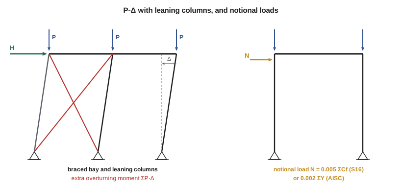
The extra moment increases the sway, which increases the moment. For a storey with lateral stiffness \(k\), the first-order drift is \(\Delta_1 = H/k\), and the second-order drift converges to
The ratio \(\sum P\,\Delta_1/(Hh)\) is the stability index of the storey. When it is small, a few per cent, second-order effects are negligible. When it approaches 1, the storey becomes unstable: the gravity loads alone are enough to keep it swaying. Real frames are also not perfectly plumb, with erection tolerances of about 1/500 of the height, so even with no lateral load the gravity loads push them sideways.
Stability in S16
S16 requires the translational load effects, the forces and moments caused by sway, to be increased for second-order effects. It accepts a second-order analysis or the amplification factor
applied to the moments and forces from lateral loads, where \(\sum C_f\) is the total factored gravity load on the storey, \(\Delta_f\) the first-order interstorey drift under the factored lateral loads, \(\sum V_f\) the factored storey shear, and \(h\) the storey height. To represent out-of-plumbness, S16 adds notional lateral loads of 0.005 times the factored gravity load at each level, in every load combination. With these effects included, the members are designed with an effective length factor \(K = 1.0\). A large \(U_2\), say above about 1.4, is a sign that the frame is too flexible and should be stiffened rather than designed for ever larger amplified forces.
For braced frames the bracing members themselves are designed for the amplified forces. The braced columns are designed as pinned members with \(K = 1.0\), and \(U_1\) from lesson 8 still applies to their own member effects.
Why the maintenance bay is braced
In its longitudinal walls, the maintenance bay has two X-braced bays, each 7.5 m wide and 6.0 m high, that resist wind on the end walls and the notional loads for the whole storey. The factored gravity load on the storey in case 4 is about 2400 kN. The specified wind load is 60 kN per braced bay.
Worked problem
Tension-only X-bracing
Design a single-angle diagonal for one braced bay, and compute the drift and \(U_2\). Only the diagonal in tension is counted; the other buckles harmlessly (lesson 4).
Show solution
- Notional load per bay: \(0.005(2400)/2 = 6.0\) kN. Factored shear: \(V_f = 1.4(60) + 6.0 = 90.0\) kN.
- Diagonal length \(\sqrt{7.5^2 + 6.0^2} = 9.60\) m, \(\cos\theta = 0.781\):
- \[T_f = \frac{90.0}{0.781} = 115\ \text{kN}\]
- Try L89x89x6.4 (350W, \(A = 1090\) mm², \(r_z = 17.5\) mm) bolted by one leg with three M20 bolts: gross yielding \(0.90(1090)(350) = 343\) kN; net fracture \(0.75(0.60)(1090 - 24 \times 6.4)(450) = 190\) kN.
- Slenderness between the end and the crossing point, where the diagonals are bolted together: \(4800/17.5 = 274 < 300\).
- Lateral stiffness of the bay with one diagonal:
- \[k = \frac{EA\cos^2\theta}{L_d} = \frac{200\,000(1090)(0.610)}{9600} = 13.8\ \text{kN/mm} \qquad \Delta_f = \frac{90.0}{13.8} = 6.5\ \text{mm}\]
- \[U_2 = \frac{1}{1 - \dfrac{2400(6.5)}{2(90.0)(6000)}} = 1.015\]
Answer: The L89x89x6.4 has \(T_r = 190\) kN against 115 kN; it is chosen for its slenderness, not its strength. Second-order effects add only 1.5 per cent, and the drift under the specified wind is 4.3 mm, about \(h/1400\).
Now compare a storey with no bracing, in which the same lateral load is resisted by two portal frames, each with two W200x46 columns pinned at the base and rigidly connected to a stiff roof beam. Each column then has a lateral stiffness of \(3EI/h^3\), only 0.126 kN/mm. The storey drifts 356 mm under the factored loads, and \(U_2 = 4.8\): the frame would be on the edge of instability. Pinned-base portals with light columns simply cannot carry the leaning gravity load of a wide roof. A small amount of bracing steel, a few hundred kilograms, gives the whole storey its stability.
Sofia's program reproduces the brace design and the comparison, and then sizes a column brace, the subject of the next section.
import math
# Maintenance bay longitudinal walls: X-braced bays (tension-only), CSA S16 clause 8.4
E, Fy, Fu = 200000.0, 350.0, 450.0
h, b = 6000.0, 7500.0                    # storey height and braced bay width (mm)
Ld = math.hypot(h, b); c = b / Ld
sum_Cf = 2400.0                          # factored gravity load on the storey, case 4 (kN)
W_bay = 60.0                             # specified wind per braced bay (kN); two bays share the storey
notional = 0.005 * sum_Cf / 2
Vf = 1.4 * W_bay + notional
Tf = Vf / c
print(f"Diagonal {Ld/1000:.2f} m, cos = {c:.3f}; Vf per bay = {Vf:.1f} kN (notional {notional:.1f}); brace Tf = {Tf:.0f} kN")

# Single angle L89x89x6.4, one leg bolted with three M20 bolts
A, t, rz = 1090.0, 6.4, 17.5
Tr = min(0.90 * A * Fy, 0.75 * 0.60 * (A - 24 * t) * Fu) / 1e3
print(f"L89x89x6.4: Tr = {Tr:.0f} kN, L/r to the crossing = {Ld/2/rz:.0f} (limit 300)")

# Lateral stiffness of one bay (one tension diagonal acting), drift and U2
k = E * A * c**2 / Ld / 1e3              # kN/mm
d_f = Vf / k
U2 = 1 / (1 - sum_Cf * d_f / (2 * Vf * h))
print(f"Bay stiffness {k:.2f} kN/mm; factored drift {d_f:.1f} mm; U2 = {U2:.3f}")
print(f"Specified wind drift = {W_bay/k:.1f} mm = h/{h/(W_bay/k):.0f}")

# The same storey with two pinned-base portal frames instead (four W200x46 columns, rigid beams)
Ic = 45.5e6
k_mf = 4 * 3 * E * Ic / h**3 / 1e3
d_mf = 2 * Vf / k_mf
ratio = sum_Cf * d_mf / (2 * Vf * h)
print(f"Moment frames: storey stiffness {k_mf:.3f} kN/mm, drift {d_mf:.0f} mm, U2 = {1/(1-ratio):.1f}")

# Winter model for a mid-height column brace: ideal stiffness 2P/Lb, provide twice, initial offset Lb/500
P, Lb = 890.0, 2250.0
beta = 2 * (2 * P / Lb)
Pb = beta * (2 * Lb / 500)
print(f"Column brace: stiffness {beta:.2f} kN/mm, force {Pb:.1f} kN = {Pb/P*100:.1f}% of P")Diagonal 9.60 m, cos = 0.781; Vf per bay = 90.0 kN (notional 6.0); brace Tf = 115 kN L89x89x6.4: Tr = 190 kN, L/r to the crossing = 274 (limit 300) Bay stiffness 13.84 kN/mm; factored drift 6.5 mm; U2 = 1.015 Specified wind drift = 4.3 mm = h/1384 Moment frames: storey stiffness 0.506 kN/mm, drift 356 mm, U2 = 4.8 Column brace: stiffness 1.58 kN/mm, force 14.2 kN = 1.6% of P
How strong and stiff must a brace be?
A brace that keeps a column or beam from buckling at an intermediate point must be both stiff enough and strong enough. George Winter showed in the 1950s that a column braced at mid-height by a spring needs an ideal spring stiffness of \(2P/L_b\) to buckle between the brace and the ends, where \(L_b\) is the distance between braces. A real column is not straight, and the brace force grows with the initial out-of-straightness \(\Delta_o\) and with the brace's own deformation. If the brace is twice the ideal stiffness, its deformation equals \(\Delta_o\), and the brace force is about \(2\beta_i\Delta_o\).
S16 bases its bracing requirements on this model, with the initial misalignment of the braced member and the stiffness of the brace. For the mezzanine column braced at mid-height, \(C_f = 890\) kN and \(L_b = 2.25\) m: twice the ideal stiffness is \(4(890)/2250 = 1.58\) kN/mm, and with \(\Delta_o = L_b/500\) the brace force is about 14 kN, 1.6 per cent of the column load. The brace must also have the stiffness, which a girt with a short span and a stiff connection usually provides, and the force must be traced into the lateral system.
Beam bracing follows the same ideas. A brace for lateral-torsional buckling either holds the compression flange, a lateral brace, or prevents twist, a torsional brace. The required force is a small fraction of the flange compression, and the stiffness requirement depends on the moment and the spacing. Several braces in a row, such as joists connected to a girder, each carry their share, and their forces accumulate in the members that anchor them.
Load paths for stability
Every brace force must reach the ground. The roof deck acts as a horizontal diaphragm that collects wind and notional loads and delivers them to the braced bays; struts and chords around the edges of the diaphragm carry the forces to the braces; the braces deliver them to the foundations as horizontal shear and as uplift and compression at the columns of the braced bay. Designers often draw this path on a plan before calculating anything, because a missing link, such as a deck that is not connected to the top of a braced bay or a strut that is only snug-bolted to a column, defeats the whole system.
Stability during erection deserves equal care. Before the deck is fixed and the braces are bolted, the frame is a set of loose columns and beams. Erectors install temporary bracing and guy cables and complete the permanent bracing early in the sequence, and the design drawings should tell them which members are part of the lateral system.
Drift limits
Stability and drift are linked: a frame that drifts little under wind also has small second-order effects. Drift under service wind is limited to protect cladding, partitions and glazing; common targets are a storey drift of about h/400 to h/500 for buildings with brittle cladding and somewhat more for industrial buildings with metal siding, and the limits for crane buildings are tighter still, because the crane wheels must stay on their rails. A braced bay easily meets these targets, as the example showed. A moment frame usually has to be sized for drift rather than strength, which is one more reason it costs more.
Seismic considerations
Earthquake design adds requirements beyond those in this course. Under strong shaking, braced frames are expected to yield in the braces while the columns and connections stay elastic, which needs capacity design and special detailing. In low-seismic regions such as Thunder Bay, the NBC permits a conventional construction category with modest detailing, and tension-only bracing like that above is common for light buildings, within limits on height and storey.
Common mistakes
MistakeDesigning columns of a braced frame for sway with K from alignment charts.
InsteadColumns in braced frames use K = 1.0; sway effects belong to the bracing.
MistakeLeaving out notional loads.
InsteadS16 requires notional loads in all combinations to represent out-of-plumbness.
MistakeChoosing a brace for strength alone.
InsteadBraces need stiffness as well as strength.
MistakeAssuming the deck delivers lateral load to the braced bay without checking the connections.
InsteadTrace the whole load path from diaphragm to foundation.
Summary and key terms
- Leaning columns rely on the lateral system; gravity loads acting on storey sway add the P-Δ moment \(\sum P\Delta\).
- S16 amplifies sway effects by \(U_2 = 1/(1 - \sum C_f\Delta_f/\sum V_fh)\), adds notional loads of 0.005 of the gravity load, and then uses K = 1.0.
- Braced bays make the maintenance bay stiff: second-order effects add only about 1.5 per cent, compared with near-instability for pinned-base portals.
- Braces need twice the ideal stiffness \(2P/L_b\) and a strength of about 1 to 2 per cent of the braced force.
- Every stability force must follow a complete load path to the foundation, during erection as well as in service.
- Leaning column
- A column pinned at both ends that carries gravity load but provides no lateral stiffness.
- P-Delta effect
- The additional storey moment from gravity loads acting on lateral drift.
- Stability index
- The ratio of the P-Δ moment to the first-order storey moment, ΣPΔ/(Hh).
- Notional load
- A small lateral load applied to represent initial out-of-plumbness.
- Amplification factor U2
- The factor that increases first-order sway effects for P-Δ.
- Direct analysis method
- A stability design method using second-order analysis with reduced stiffness and notional loads.
- Diaphragm
- A floor or roof acting as a horizontal beam that delivers lateral loads to the vertical system.
- Ideal brace stiffness
- The stiffness at which a braced member just buckles between braces.
Practice problems
Work each problem on paper first, then reveal the answer to check.
A storey has \(\sum C_f = 5000\) kN, \(\sum V_f = 200\) kN, \(h = 4.0\) m and \(\Delta_f = 10\) mm. Find \(U_2\).
Show answer
\(5000(10)/(200 \times 4000) = 0.0625\); \(U_2 = 1/0.9375 = 1.07\).
Why is the compression diagonal of light X-bracing ignored?
Show answer
Its slenderness is so high that it buckles at a very small load, so it contributes almost nothing.
What happens to the required brace stiffness if the distance between braces halves?
Show answer
It doubles, because the ideal stiffness is 2P/Lb.
Name three links in the load path from roof wind to foundation.
Show answer
Roof diaphragm, collector strut to the braced bay, brace diagonals, and the column and anchor rods of the braced bay.
Lesson quiz · 5 questions
Score 60% or more to complete this lesson.
Create a free account to save your progress, take quizzes and earn a certificate.